Arduino Uno R4 WiFi contrôle le relais via le Web
Dans ce tutoriel, nous allons apprendre à contrôler un relais via une interface Web accessible à partir d'un navigateur sur un PC ou un smartphone. Nous utilizarons la carte Arduino Uno R4 WiFi, qui sera programmée pour fonctionner comme un serveur Web. Supposons que l'adresse IP de l'Arduino Uno R4 WiFi soit 192.168.0.2. Voici comment cela fonctionne :
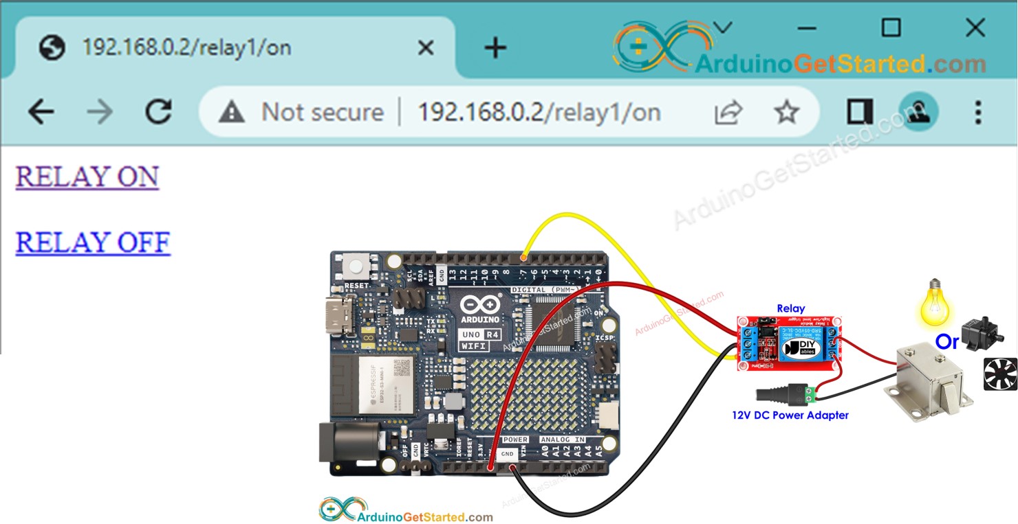
- Pour accéder à l'interface Web, il suffit de saisir 192.168.0.2 dans la barre d'adresse de votre navigateur. Cela enverra une requête à l'Arduino et, en réponse, l'Arduino fournira une page Web contenant un bouton marche/arrêt pour piloter le relais.
- De même, si vous cliquez sur le bouton RELAIS ALLUMÉ sur la page Web ou saisissez 192.168.0.2/relay1/on dans le navigateur Web, l'Arduino activera le relais et répondra avec la page Web mise à jour.
- De même, si vous cliquez sur le bouton RELAIS ÉTEINT sur la page Web ou saisissez 192.168.0.2/relay1/off dans le navigateur Web, l'Arduino désactivera le relais et répondra avec la page Web mise à jour.
En connectant un relais à des dispositifs tels qu'une serrure électromagnétique, une ampoule, un ruban LED, un moteur ou un actionneur, nous pouvons les contrôler via une interface Web.
Le tutoriel fournit une base que vous pouvez facilement et de manière créative personnaliser pour accomplir ce qui suit :
- Contrôlez plusieurs relais via une interface Web.
- Reconcevez l'interface utilisateur Web pour l'adapter selon vos préférences.
Préparation du matériel
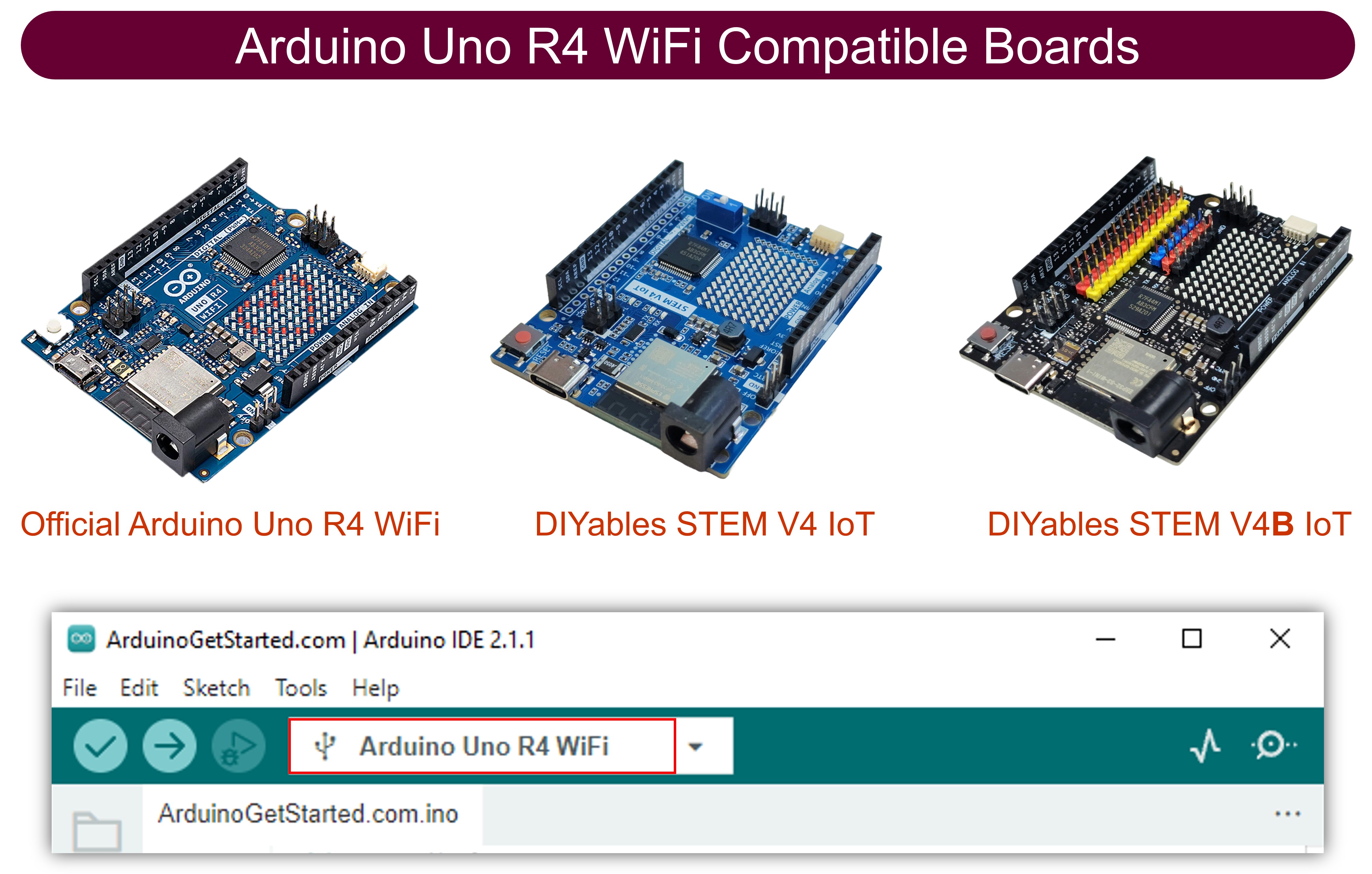
Ou vous pouvez acheter les kits suivants:
| 1 | × | Kit de Démarrage DIYables STEM V4 IoT (Arduino inclus) | |
| 1 | × | Kit de Capteurs DIYables (18 capteurs/écrans) |
À propos du relais et de l'Arduino Uno R4
Si vous ne connaissez pas l'Arduino Uno R4 et le relais (répartition des broches, fonctionnement, programmation, etc.), renseignez-vous sur eux dans les tutoriels suivants :
Diagramme de câblage
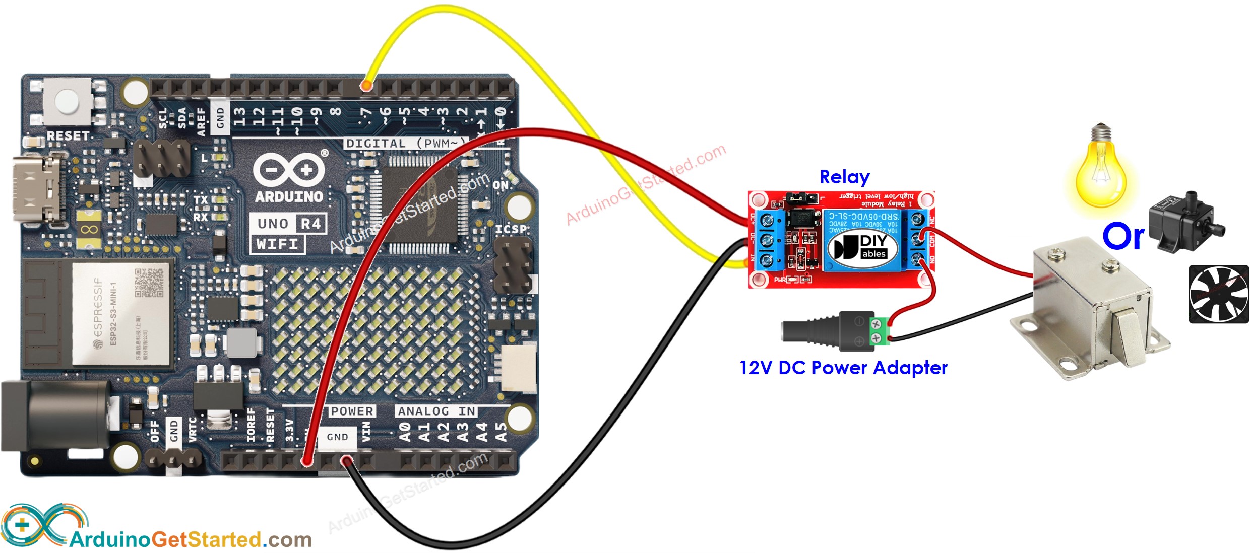
Cette image a été créée avec Fritzing. Cliquez pour agrandir l'image.
Code Arduino
Étapes rapides
- Si c'est la première fois que vous utilisez Arduino Uno R4, consultez Comment démarrer avec Arduino Uno R4..
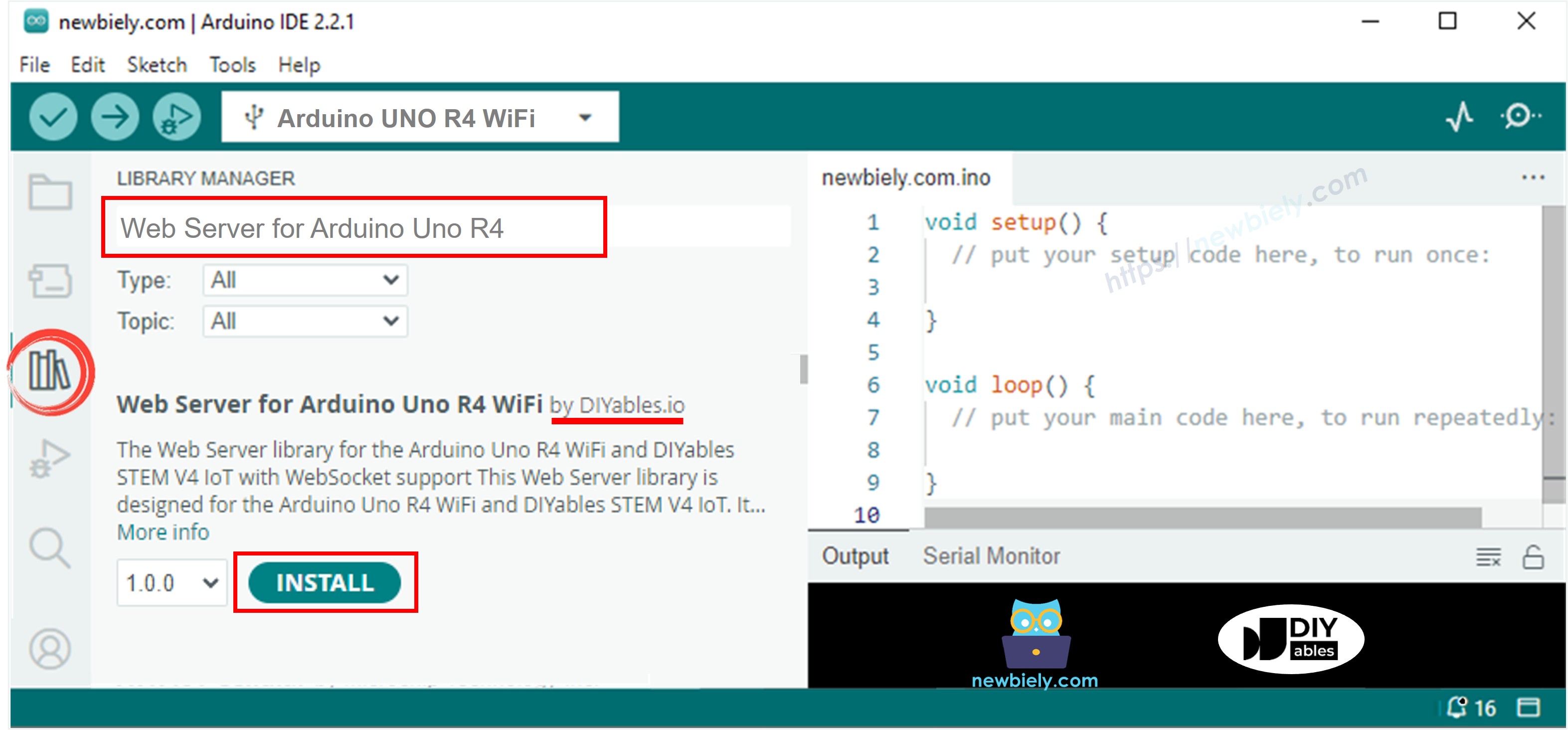
- Ouvrez le Gestionnaire de bibliothèques en cliquant sur l'icône Gestionnaire de bibliothèques sur le côté gauche de l'IDE Arduino.
- Recherchez le Serveur Web pour Arduino Uno R4 WiFi et localisez la bibliothèque Serveur Web créée par DIYables.
- Cliquez sur le bouton Install pour ajouter la bibliothèque Serveur Web.
- Copiez le code ci-dessus et ouvrez-le dans l’IDE Arduino
- Modifiez dans le code les informations Wi‑Fi (SSID et mot de passe) pour les mettre à votre configuration
- Cliquez sur le bouton Upload dans l’IDE Arduino pour téléverser le code sur l’Arduino
- Ouvrez le moniteur série
- Vérifiez le résultat dans le moniteur série
- Vous verrez une adresse IP, par exemple : 192.168.0.2. C'est l'adresse IP du serveur Web Arduino.
- Ouvrez un navigateur web et saisissez l'un des trois formats ci-dessous dans la barre d'adresse :
- Veuillez noter que l'adresse IP peut être différente. Assurez-vous de vérifier la valeur actuelle sur le Moniteur Série.
- De plus, vous observerez la sortie suivante sur le Moniteur Série.
- Vérifiez l'état du relais
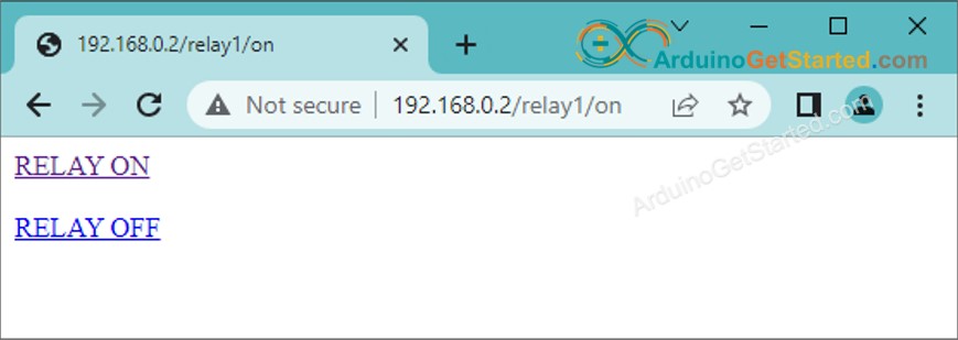
- Vous verrez la page Web de la carte Arduino dans le navigateur comme ci-dessous :
Vous avez désormais la capacité de contrôler l'état marche/arrêt du relais via l'interface web. Vous pouvez également personnaliser facilement et de manière créative le code afin d'accomplir ce qui suit :
- Contrôler plusieurs relais via une interface Web.
- Reconcevoir l'interface utilisateur Web pour l'adapter à vos préférences.
Si vous souhaitez améliorer l'apparence de la page Web avec une interface utilisateur graphique impressionnante (UI), vous pouvez vous référer au tutoriel Arduino - Serveur Web. pour l'inspiration et des conseils.