Arduino - Actionneur avec retour d'information
Dans un tutoriel précédent, nous avons appris à propos de l'actionneur linéaire sans retour d'information (BASE_URL/tutorials/arduino/arduino-actuator). Dans ce tutoriel, nous allons apprendre sur l'actionneur linéaire avec retour d'information (également appelé actionneur linéaire à retour d'information). Le retour d'information de l'actionneur linéaire fournit les informations nécessaires pour identifier la position de sa course, et ensuite contrôler la position. Plus en détail, nous allons apprendre :
- Comment fonctionne un actionneur linéaire à retour d'information
- Comment trouver la position de l'actionneur linéaire à retour d'information (en millimètres)
- Comment contrôler la position d'un actionneur linéaire
Préparation du matériel
Ou vous pouvez acheter les kits suivants:
| 1 | × | Kit de Démarrage DIYables STEM V3 (Arduino inclus) | |
| 1 | × | Kit de Capteurs DIYables (18 capteurs/écrans) |
À propos de l'actionneur linéaire à retour d'information
Un actionneur linéaire à retour d'information est un actionneur linéaire qui possède un signal de retour permettant d'identifier sa position et de la contrôler. Le retour est un potentiomètre qui délivre une valeur de tension proportionnelle à la position de la course.
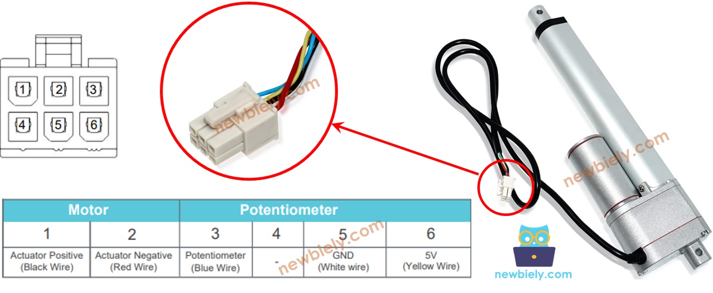
Brochage de l'actionneur linéaire de rétroaction
Un actionneur linéaire à retour d'information possède 5 fils :
- Fil positif de l'actionneur : Ce fil est utilisé pour contrôler l'actionneur linéaire en utilisant une haute tension (12V, 24V, 48V...).
- Fil de 5V : ce fil est utilisé pour le potentiomètre de retour. Connectez ce fil à 5V ou 3.3V.
- Fil de masse : ce fil est utilisé pour le potentiomètre de retour. Connectez ce fil à la masse.
- Fil de potentiomètre : (également appelé fil de retour, ou fil de sortie) ce fil émet une valeur de tension proportionnelle à la position de la course.
Comment ça fonctionne
Si nous fournissons une haute tension aux fils positifs et négatifs, la course de l'actionneur sera étendue ou rétractée. En détail, si nous connectons :
- 12V (12V, 24V, 48V...) et GND au fil positif et au fil négatif, respectivement : l'actionneur linéaire s'étend à pleine vitesse jusqu'à ce qu'il atteigne la limite.
- 12V (12V, 24V, 48V...) et GND au fil négatif et au fil positif, respectivement : l'actionneur linéaire se rétracte à pleine vitesse jusqu'à ce qu'il atteigne la limite.
- Lors de l'extension ou de la rétraction, si nous arrêtons l'alimentation de l'actionneur (GND sur les fils positif et négatif), l'actionneur cesse de s'étendre/se rétracter.
※ Note:
- La valeur de tension pour contrôler l'actionneur dépend de la spécification de l'actionneur. Consultez la fiche technique ou le manuel pour connaître la valeur de tension correspondante.
- L'actionneur peut maintenir la position même lorsqu'il cesse d'être alimenté tout en portant une charge.
La valeur de tension dans le fil du potentiomètre est proportionnelle à la position de la course sur l'actionneur. En mesurant cette tension, nous pouvons connaître la position de la course.
Schéma de câblage
Veuillez retirer les trois cavaliers sur le module L298N avant de procéder au câblage.
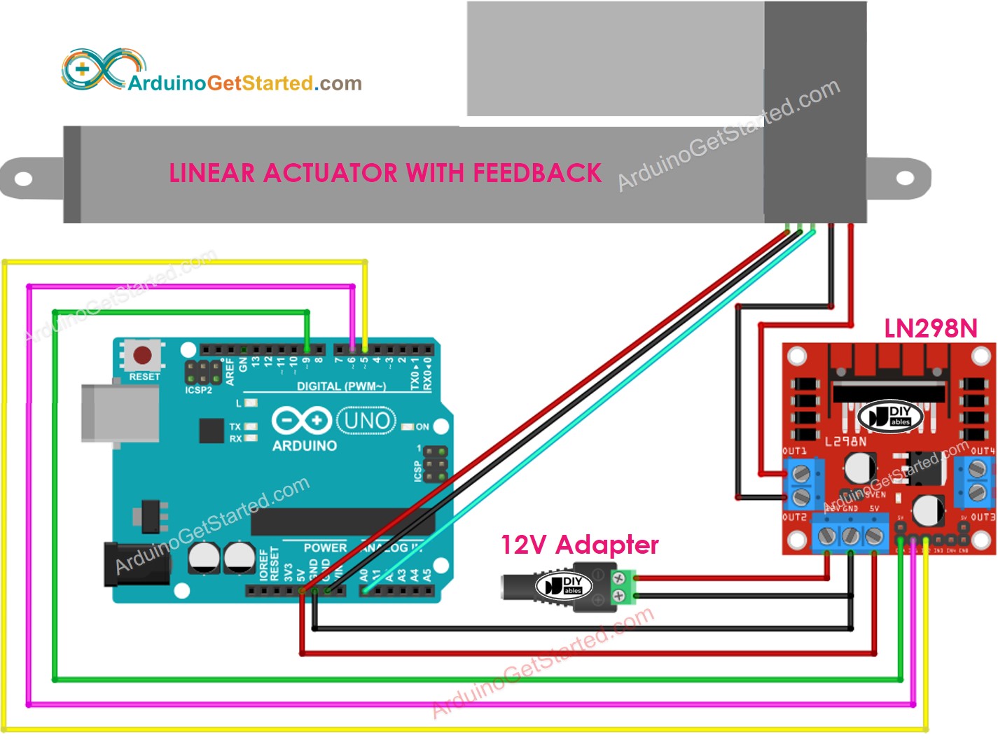
Cette image a été créée avec Fritzing. Cliquez pour agrandir l'image.
Comment contrôler l'extension/la rétraction d'un actionneur linéaire
Consultez le tutoriel Arduino - Actionneur.
Comment trouver la position de l'actionneur linéaire
Ce qui suit montre comment identifier la position du vérin sur un actionneur linéaire.
Étalonnage
- Identifiez la longueur de la course de l'actionneur (en millimètres) en mesurant (à l'aide d'une règle) ou en consultant la fiche technique
- Identifiez les valeurs de sortie lorsque l'actionneur linéaire est entièrement étendu et entièrement rétracté en exécutant le code ci-dessous
- Vous verrez le journal sur le moniteur série comme dans l'exemple ci-dessous.
- Notez ces valeurs
- Si les valeurs min/max sont inversées, échangez IN1_PIN et IN2_PIN
Code Arduino qui calcule la position de l'actionneur
- Mettez à jour les trois valeurs calibrées dans le code
- Téléchargez le code sur Arduino
- Voir le résultat sur le moniteur série