Arduino - Feu de circulation
Dans ce tutoriel, nous allons apprendre à utiliser Arduino pour contrôler le module de feu de circulation. En détail, nous apprendrons :
Comment connecter le module de feu de circulation à Arduino
Comment programmer Arduino pour contrôler le module de feu de circulation RGB
Comment programmer Arduino pour contrôler le module de feu de circulation RGB sans utiliser la fonction delay()
Ou vous pouvez acheter les kits suivants:
Divulgation : Certains des liens fournis dans cette section sont des liens affiliés Amazon. Nous pouvons recevoir une commission pour tout achat effectué via ces liens, sans coût supplémentaire pour vous. Nous vous remercions de votre soutien.
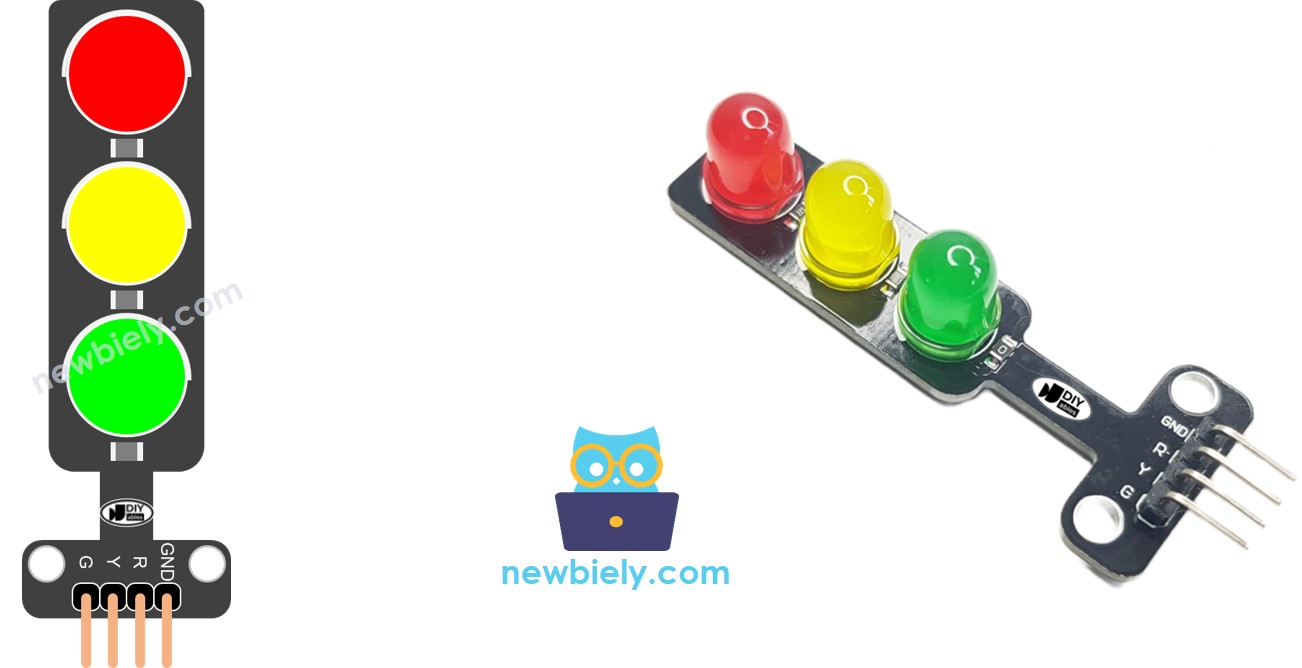
Un module de feu de circulation comprend 4 broches :
Broche GND : La broche de masse, connectez cette broche au GND de l'Arduino.
Broche R : La broche pour contrôler la lumière rouge, connectez cette broche à une sortie numérique de l'Arduino.
Broche Y : La broche pour contrôler la lumière jaune, connectez cette broche à une sortie numérique de l'Arduino.
Broche G : La broche pour contrôler la lumière verte, connectez cette broche à une sortie numérique de l'Arduino.
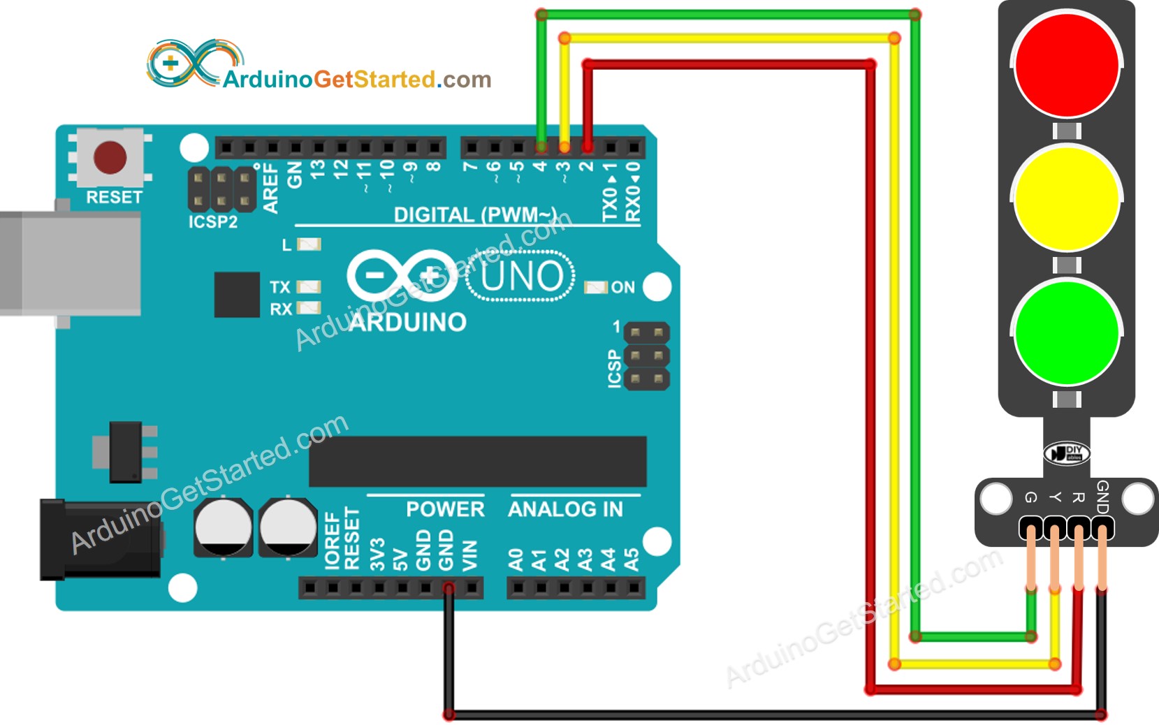
Cette image a été créée avec Fritzing. Cliquez pour agrandir l'image.
#define PIN_RED 2
#define PIN_YELLOW 3
#define PIN_GREEN 4
#define RED_TIME 4000
#define YELLOW_TIME 4000
#define GREEN_TIME 4000
void setup() {
pinMode(PIN_RED, OUTPUT);
pinMode(PIN_YELLOW, OUTPUT);
pinMode(PIN_GREEN, OUTPUT);
}
void loop() {
digitalWrite(PIN_RED, HIGH);
digitalWrite(PIN_YELLOW, LOW);
digitalWrite(PIN_GREEN, LOW);
delay(RED_TIME);
digitalWrite(PIN_RED, LOW);
digitalWrite(PIN_YELLOW, HIGH);
digitalWrite(PIN_GREEN, LOW);
delay(YELLOW_TIME);
digitalWrite(PIN_RED, LOW);
digitalWrite(PIN_YELLOW, LOW);
digitalWrite(PIN_GREEN, HIGH);
delay(GREEN_TIME);
}
Copiez le code ci-dessus et ouvrez-le avec Arduino IDE
Cliquez sur le bouton Upload dans Arduino IDE pour téléverser le code sur Arduino
Vérifiez le module de feu de circulation
image source: diyables.io
Il est important de noter que le fonctionnement exact d'un feu de circulation peut varier en fonction du design spécifique et de la technologie utilisée dans différentes régions et intersections. Les principes décrits ci-dessus fournissent une compréhension générale de la manière dont les feux de circulation fonctionnent pour gérer le trafic et améliorer la sécurité sur les routes.
Le code ci-dessus démontre la gestion individuelle de l'éclairage. Améliorons maintenant le code pour une meilleure optimisation.
#define PIN_RED 2
#define PIN_YELLOW 3
#define PIN_GREEN 4
#define RED_TIME 2000
#define YELLOW_TIME 1000
#define GREEN_TIME 2000
#define RED 0
#define YELLOW 1
#define GREEN 2
const int pins[] = { PIN_RED, PIN_YELLOW, PIN_GREEN };
const int times[] = { RED_TIME, YELLOW_TIME, GREEN_TIME };
void setup() {
pinMode(PIN_RED, OUTPUT);
pinMode(PIN_YELLOW, OUTPUT);
pinMode(PIN_GREEN, OUTPUT);
}
void loop() {
trafic_light_on(RED);
delay(times[RED]);
trafic_light_on(YELLOW);
delay(times[YELLOW]);
trafic_light_on(GREEN);
delay(times[GREEN]);
}
void trafic_light_on(int light) {
for (int i = RED; i <= GREEN; i++) {
if (i == light)
digitalWrite(pins[i], HIGH);
else
digitalWrite(pins[i], LOW);
}
}
#define PIN_RED 2
#define PIN_YELLOW 3
#define PIN_GREEN 4
#define RED_TIME 2000
#define YELLOW_TIME 1000
#define GREEN_TIME 2000
#define RED 0
#define YELLOW 1
#define GREEN 2
const int pins[] = {PIN_RED, PIN_YELLOW, PIN_GREEN};
const int times[] = {RED_TIME, YELLOW_TIME, GREEN_TIME};
void setup() {
pinMode(PIN_RED, OUTPUT);
pinMode(PIN_YELLOW, OUTPUT);
pinMode(PIN_GREEN, OUTPUT);
}
void loop() {
for (int light = RED; light <= GREEN; light ++) {
trafic_light_on(light);
delay(times[light]);
}
}
void trafic_light_on(int light) {
for (int i = RED; i <= GREEN; i ++) {
if (i == light)
digitalWrite(pins[i], HIGH);
else
digitalWrite(pins[i], LOW);
}
}
#define PIN_RED 2
#define PIN_YELLOW 3
#define PIN_GREEN 4
#define RED_TIME 2000
#define YELLOW_TIME 1000
#define GREEN_TIME 2000
#define RED 0
#define YELLOW 1
#define GREEN 2
const int pins[] = { PIN_RED, PIN_YELLOW, PIN_GREEN };
const int times[] = { RED_TIME, YELLOW_TIME, GREEN_TIME };
unsigned long last_time = 0;
int light = RED;
void setup() {
pinMode(PIN_RED, OUTPUT);
pinMode(PIN_YELLOW, OUTPUT);
pinMode(PIN_GREEN, OUTPUT);
trafic_light_on(light);
last_time = millis();
}
void loop() {
if ((millis() - last_time) > times[light]) {
light++;
if (light >= 3)
light = RED;
trafic_light_on(light);
last_time = millis();
}
}
void trafic_light_on(int light) {
for (int i = RED; i <= GREEN; i++) {
if (i == light)
digitalWrite(pins[i], HIGH);
else
digitalWrite(pins[i], LOW);
}
}
※ NOS MESSAGES
N'hésitez pas à partager le lien de ce tutoriel. Cependant, veuillez ne pas utiliser notre contenu sur d'autres sites web. Nous avons investi beaucoup d'efforts et de temps pour créer ce contenu, veuillez respecter notre travail !