ESP32 Bluetooth Broches Numériques - Tutoriel Interface de Contrôle et Surveillance des Broches
Aperçu
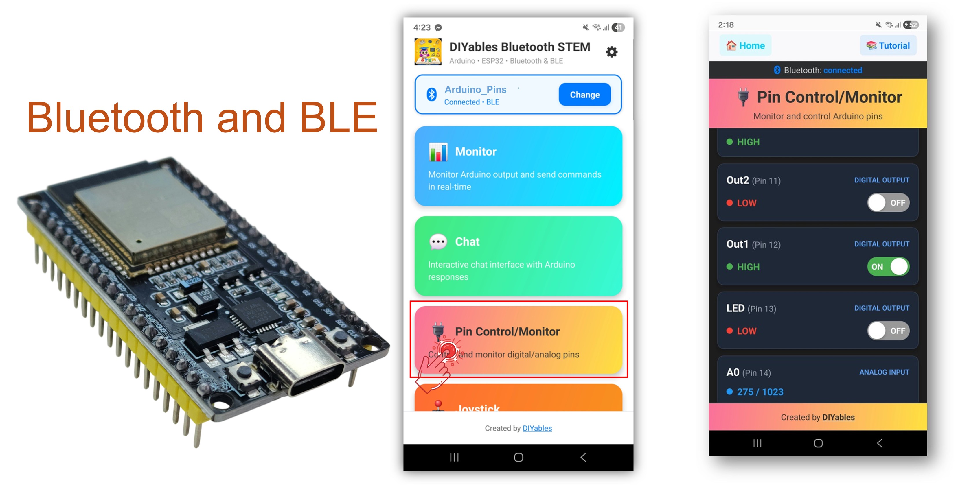
L'exemple Bluetooth Broches Numériques fournit un contrôle à distance et une surveillance des broches GPIO de l'ESP32 via l'application DIYables Bluetooth STEM. Conçu pour les cartes ESP32 avec support pour les connexions BLE (Bluetooth Low Energy) et Bluetooth Classique. Configurez les broches comme entrées ou sorties, basculez les broches de sortie, lisez les états d'entrées numériques et analogiques, et recevez des notifications en temps réel des changements de broches — parfait pour la domotique, le contrôle de relais, la surveillance de boutons, et la lecture de capteurs.
Cet exemple supporte deux modes Bluetooth :
ESP32 BLE (Bluetooth Low Energy) : Fonctionne sur Android et iOS
ESP32 Bluetooth Classique : Fonctionne sur Android uniquement. iOS ne supporte pas le Bluetooth Classique. Utilisez BLE si vous avez besoin du support iOS.
Fonctionnalités
Contrôle de Broches de Sortie : Basculez les broches de sortie numériques HIGH/LOW depuis l'application
Surveillance de Broches d'Entrée : Lisez les états des broches d'entrée numériques et analogiques
Noms de Broches Personnalisés : Attribuez des noms conviviaux à chaque broche (ex. "LED", "Btn1", "A34")
Mises à Jour en Temps Réel : Notifications automatiques lorsque les états des broches d'entrée changent
Jusqu'à 16 Broches : Support pour jusqu'à 16 broches configurables simultanément
Modes Mixtes : Combinez broches d'entrée et de sortie dans la même configuration
BLE & Bluetooth Classique : Choisissez le mode Bluetooth qui convient à votre projet
Multi-plateforme : Le mode BLE fonctionne sur Android et iOS ; le Bluetooth Classique fonctionne sur Android
Divulgation : Certains des liens fournis dans cette section sont des liens affiliés Amazon. Nous pouvons recevoir une commission pour tout achat effectué via ces liens, sans coût supplémentaire pour vous. Nous vous remercions de votre soutien.
Connectez la carte ESP32 à votre ordinateur en utilisant un câble USB.
Lancez l'Arduino IDE sur votre ordinateur.
Sélectionnez la carte ESP32 appropriée et le port COM.
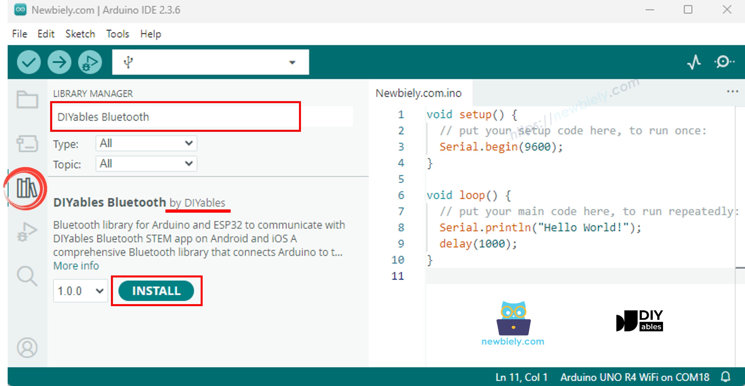
Naviguez vers l'icône Libraries dans la barre de gauche de l'Arduino IDE.
Recherchez "DIYables Bluetooth", puis trouvez la librairie DIYables Bluetooth par DIYables
Cliquez sur le bouton Install pour installer la librairie.
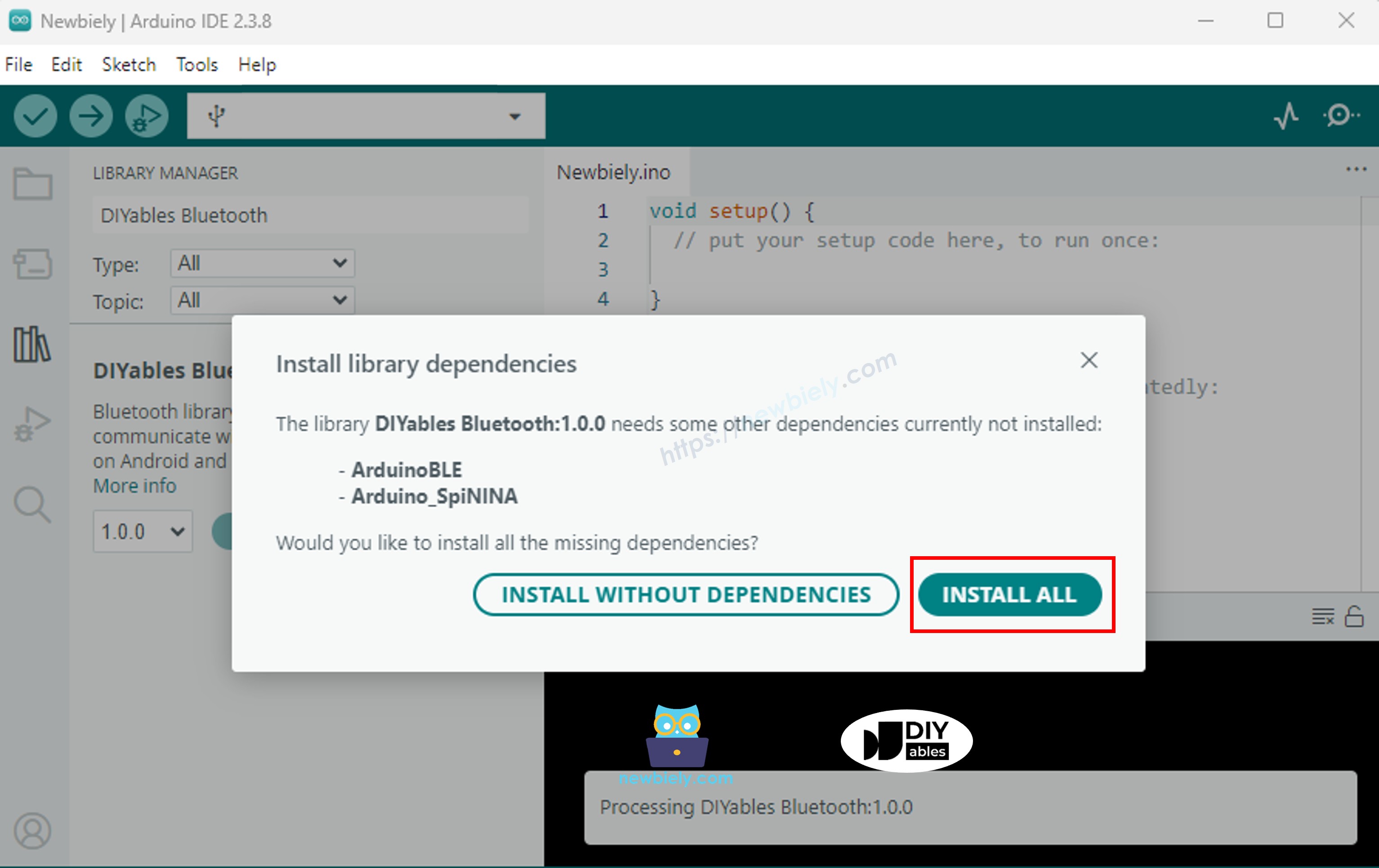
Il vous sera demandé d'installer d'autres dépendances de librairie
Cliquez sur le bouton Install All pour installer toutes les dépendances de librairie.
Choisissez l'un des deux modes Bluetooth ci-dessous selon vos besoins :
Code ESP32 Bluetooth Classique (fonctionne avec l'application sur Android uniquement)
Note : Le Bluetooth Classique n'est PAS supporté sur iOS. Si vous avez besoin du support iOS, utilisez le code BLE ci-dessous.
Dans l'Arduino IDE, allez à File Examples DIYables Bluetooth Esp32Bluetooth_PinControl exemple, ou copiez le code ci-dessus et collez-le dans l'éditeur de l'Arduino IDE
/* * DIYables Bluetooth Library - ESP32 Classic Bluetooth Pin Control Example * Works with DIYables Bluetooth STEM app on Android * Note: Classic Bluetooth is NOT supported on iOS. Use BLE examples for iOS support. * * This example demonstrates the Bluetooth Pin Control/Monitor feature: * - Control digital output pins via Bluetooth * - Monitor digital input pins * - Monitor analog input pins * - Configure pin modes (INPUT/OUTPUT) * * Compatible Boards: * - ESP32 (all variants with Classic Bluetooth) * - ESP32-WROOM-32 * - ESP32-DevKitC * - ESP32-WROVER * * Note: Select "Huge APP (3MB No OTA/1MB SPIFFS)" partition scheme * in Arduino IDE: Tools > Partition Scheme * * Setup: * 1. Upload the sketch to your ESP32 * 2. Open Serial Monitor (115200 baud) to see connection status * 3. Use DIYables Bluetooth App to connect and control pins * * Tutorial: https://diyables.io/bluetooth-app * Author: DIYables */#include <DIYables_BluetoothServer.h>#include <DIYables_BluetoothPinControl.h>#include <platforms/DIYables_Esp32Bluetooth.h>// Create Bluetooth instancesDIYables_Esp32Bluetooth bluetooth("ESP32_Pins");DIYables_BluetoothServer bluetoothServer(bluetooth);// Create Pin Control/Monitor app instanceDIYables_BluetoothPinControl bluetoothPins;// Pin configuration (adjust for your ESP32 board)constint LED_PIN = 2; // Built-in LED on most ESP32 boardsconstint OUTPUT_PIN_1 = 16;constint OUTPUT_PIN_2 = 17;constint INPUT_PIN_1 = 18;constint INPUT_PIN_2 = 19;constint ANALOG_PIN_1 = 34; // ESP32 ADC1 pins (input only)constint ANALOG_PIN_2 = 35;voidsetup() {Serial.begin(115200);delay(1000);Serial.println("DIYables Bluetooth - ESP32 Pin Control/Monitor Example");// Initialize pinspinMode(LED_PIN, OUTPUT);pinMode(OUTPUT_PIN_1, OUTPUT);pinMode(OUTPUT_PIN_2, OUTPUT);pinMode(INPUT_PIN_1, INPUT_PULLUP);pinMode(INPUT_PIN_2, INPUT_PULLUP);// Initialize Bluetooth server with platform-specific implementation bluetoothServer.begin();// Add digital pins app to server bluetoothServer.addApp(&bluetoothPins);// Configure which pins are accessible via Bluetooth with custom names bluetoothPins.enablePin(LED_PIN, BT_PIN_OUTPUT, "LED"); bluetoothPins.enablePin(OUTPUT_PIN_1, BT_PIN_OUTPUT, "Out1"); bluetoothPins.enablePin(OUTPUT_PIN_2, BT_PIN_OUTPUT, "Out2"); bluetoothPins.enablePin(INPUT_PIN_1, BT_PIN_INPUT, "Btn1"); bluetoothPins.enablePin(INPUT_PIN_2, BT_PIN_INPUT, "Btn2"); bluetoothPins.enablePin(ANALOG_PIN_1, BT_PIN_INPUT, "A34"); bluetoothPins.enablePin(ANALOG_PIN_2, BT_PIN_INPUT, "A35");// Set up connection event callbacks bluetoothServer.setOnConnected([]() {Serial.println("Bluetooth connected!"); }); bluetoothServer.setOnDisconnected([]() {Serial.println("Bluetooth disconnected!"); });// Set up callback for pin write commands bluetoothPins.onPinWrite([](int pin, int state) {digitalWrite(pin, state);Serial.print("Pin ");Serial.print(pin);Serial.print(" set to ");Serial.println(state ? "HIGH" : "LOW"); });// Set up callback for pin read commands bluetoothPins.onPinRead([](int pin) -> int {// Read analog pins with analogRead, digital pins with digitalReadint state;if (pin == ANALOG_PIN_1 || pin == ANALOG_PIN_2) { state = analogRead(pin);Serial.print("Analog pin ");Serial.print(pin);Serial.print(" read: ");Serial.println(state); } else { state = digitalRead(pin);Serial.print("Digital pin ");Serial.print(pin);Serial.print(" read: ");Serial.println(state ? "HIGH" : "LOW"); }return state; });// Set up callback for pin mode changes bluetoothPins.onPinModeChange([](int pin, int mode) {pinMode(pin, mode == BT_PIN_OUTPUT ? OUTPUT : INPUT_PULLUP);Serial.print("Pin ");Serial.print(pin);Serial.print(" mode changed to ");Serial.println(mode == BT_PIN_OUTPUT ? "OUTPUT" : "INPUT"); });Serial.println("Waiting for Bluetooth connection...");Serial.print("Enabled pins: ");Serial.println(bluetoothPins.getEnabledPinCount());}voidloop() {// Handle Bluetooth server communications bluetoothServer.loop();// Optional: Monitor input pins and send updatesstaticunsignedlong lastInputCheck = 0;staticint lastInputState1 = HIGH;staticint lastInputState2 = HIGH;staticint lastAnalogState1 = 0;staticint lastAnalogState2 = 0;if (millis() - lastInputCheck >= 100) { lastInputCheck = millis();// Check digital input pin 1int currentState1 = digitalRead(INPUT_PIN_1);if (currentState1 != lastInputState1) { lastInputState1 = currentState1; bluetoothPins.updatePinState(INPUT_PIN_1, currentState1);Serial.print("Input pin ");Serial.print(INPUT_PIN_1);Serial.print(" changed to ");Serial.println(currentState1 ? "HIGH" : "LOW"); }// Check digital input pin 2int currentState2 = digitalRead(INPUT_PIN_2);if (currentState2 != lastInputState2) { lastInputState2 = currentState2; bluetoothPins.updatePinState(INPUT_PIN_2, currentState2);Serial.print("Input pin ");Serial.print(INPUT_PIN_2);Serial.print(" changed to ");Serial.println(currentState2 ? "HIGH" : "LOW"); }// Check analog input 1 (send update if changed by more than 50 - ESP32 has 12-bit ADC)int currentAnalog1 = analogRead(ANALOG_PIN_1);if (abs(currentAnalog1 - lastAnalogState1) > 50) { lastAnalogState1 = currentAnalog1; bluetoothPins.updatePinState(ANALOG_PIN_1, currentAnalog1);Serial.print("Analog pin ");Serial.print(ANALOG_PIN_1);Serial.print(" changed to ");Serial.println(currentAnalog1); }// Check analog input 2 (send update if changed by more than 50)int currentAnalog2 = analogRead(ANALOG_PIN_2);if (abs(currentAnalog2 - lastAnalogState2) > 50) { lastAnalogState2 = currentAnalog2; bluetoothPins.updatePinState(ANALOG_PIN_2, currentAnalog2);Serial.print("Analog pin ");Serial.print(ANALOG_PIN_2);Serial.print(" changed to ");Serial.println(currentAnalog2); } }delay(10);}
Cliquez sur le bouton Upload dans l'Arduino IDE pour téléverser le code sur l'ESP32
Ouvrez le Moniteur Série
Vérifiez le résultat dans le Moniteur Série. Il ressemble à ceci :
Newbiely | Arduino IDE 2.3.8
──
☐
✕
File
Edit
Sketch
Tools
Help
ESP32 Dev Module
Newbiely.ino
···
8Serial.println("Hello World!");
Output
Serial Monitor
Message (Enter to send message to 'ESP32 Dev Module' on 'COM15')
New Line
9600 baud
DIYables Bluetooth - ESP32 Pin Control/Monitor Example
Waiting for Bluetooth connection...
Enabled pins: 7
Ln 11, Col 1
ESP32 Dev Module on COM15
2
Code ESP32 BLE (fonctionne avec l'application sur Android et iOS)
Dans l'Arduino IDE, allez à File Examples DIYables Bluetooth Esp32BLE_PinControl exemple, ou copiez le code ci-dessus et collez-le dans l'éditeur de l'Arduino IDE
/* * DIYables Bluetooth Library - ESP32 BLE Pin Control/Monitor Example * Works with DIYables Bluetooth STEM app on Android and iOS * * This example demonstrates the Bluetooth Pin Control/Monitor feature: * - Control digital output pins via Bluetooth * - Monitor digital input pins * - Monitor analog input pins * - Configure pin modes (INPUT/OUTPUT) * * Compatible Boards: * - ESP32-WROOM-32 * - ESP32-DevKitC * - ESP32-WROVER * - ESP32-S3 * - ESP32-C3 * - Any ESP32 board supporting BLE * * Note: Select "Huge APP (3MB No OTA/1MB SPIFFS)" partition scheme * in Arduino IDE: Tools > Partition Scheme * * Setup: * 1. Upload the sketch to your ESP32 * 2. Open Serial Monitor (115200 baud) to see connection status * 3. Use DIYables Bluetooth App to connect and control pins * * Tutorial: https://diyables.io/bluetooth-app * Author: DIYables */#include <DIYables_BluetoothServer.h>#include <DIYables_BluetoothPinControl.h>#include <platforms/DIYables_Esp32BLE.h>// BLE Configurationconst char* DEVICE_NAME = "ESP32BLE_Pins";const char* SERVICE_UUID = "19B10000-E8F2-537E-4F6C-D104768A1214";const char* TX_UUID = "19B10001-E8F2-537E-4F6C-D104768A1214";const char* RX_UUID = "19B10002-E8F2-537E-4F6C-D104768A1214";// Create Bluetooth instancesDIYables_Esp32BLE bluetooth(DEVICE_NAME, SERVICE_UUID, TX_UUID, RX_UUID);DIYables_BluetoothServer bluetoothServer(bluetooth);// Create Pin Control/Monitor app instanceDIYables_BluetoothPinControl bluetoothPins;// Pin configuration (ESP32 GPIOs)constint LED_PIN = 2; // Built-in LEDconstint OUTPUT_PIN_1 = 16;constint OUTPUT_PIN_2 = 17;constint INPUT_PIN_1 = 25;constint INPUT_PIN_2 = 26;constint ANALOG_PIN_1 = 34; // Input-only ADC pinconstint ANALOG_PIN_2 = 35; // Input-only ADC pinvoidsetup() {Serial.begin(115200);delay(1000);Serial.println("DIYables Bluetooth - ESP32 BLE Pin Control/Monitor Example");// Initialize pinspinMode(LED_PIN, OUTPUT);pinMode(OUTPUT_PIN_1, OUTPUT);pinMode(OUTPUT_PIN_2, OUTPUT);pinMode(INPUT_PIN_1, INPUT_PULLUP);pinMode(INPUT_PIN_2, INPUT_PULLUP);// Initialize Bluetooth server with platform-specific implementation bluetoothServer.begin();// Add digital pins app to server bluetoothServer.addApp(&bluetoothPins);// Configure which pins are accessible via Bluetooth with custom names bluetoothPins.enablePin(LED_PIN, BT_PIN_OUTPUT, "LED"); bluetoothPins.enablePin(OUTPUT_PIN_1, BT_PIN_OUTPUT, "Out1"); bluetoothPins.enablePin(OUTPUT_PIN_2, BT_PIN_OUTPUT, "Out2"); bluetoothPins.enablePin(INPUT_PIN_1, BT_PIN_INPUT, "Btn1"); bluetoothPins.enablePin(INPUT_PIN_2, BT_PIN_INPUT, "Btn2"); bluetoothPins.enablePin(ANALOG_PIN_1, BT_PIN_INPUT, "A34"); bluetoothPins.enablePin(ANALOG_PIN_2, BT_PIN_INPUT, "A35");// Set up connection event callbacks bluetoothServer.setOnConnected([]() {Serial.println("Bluetooth connected!"); }); bluetoothServer.setOnDisconnected([]() {Serial.println("Bluetooth disconnected!"); });// Set up callback for pin write commands bluetoothPins.onPinWrite([](int pin, int state) {digitalWrite(pin, state);Serial.print("Pin ");Serial.print(pin);Serial.print(" set to ");Serial.println(state ? "HIGH" : "LOW"); });// Set up callback for pin read commands bluetoothPins.onPinRead([](int pin) -> int {int state;if (pin == ANALOG_PIN_1 || pin == ANALOG_PIN_2) { state = analogRead(pin);Serial.print("Analog pin ");Serial.print(pin);Serial.print(" read: ");Serial.println(state); } else { state = digitalRead(pin);Serial.print("Digital pin ");Serial.print(pin);Serial.print(" read: ");Serial.println(state ? "HIGH" : "LOW"); }return state; });// Set up callback for pin mode changes bluetoothPins.onPinModeChange([](int pin, int mode) {pinMode(pin, mode == BT_PIN_OUTPUT ? OUTPUT : INPUT_PULLUP);Serial.print("Pin ");Serial.print(pin);Serial.print(" mode changed to ");Serial.println(mode == BT_PIN_OUTPUT ? "OUTPUT" : "INPUT"); });Serial.println("Waiting for Bluetooth connection...");Serial.print("Enabled pins: ");Serial.println(bluetoothPins.getEnabledPinCount());}voidloop() { bluetoothServer.loop();staticunsignedlong lastInputCheck = 0;staticint lastInputState1 = HIGH;staticint lastInputState2 = HIGH;staticint lastAnalogState1 = 0;staticint lastAnalogState2 = 0;if (millis() - lastInputCheck >= 100) { lastInputCheck = millis();int currentState1 = digitalRead(INPUT_PIN_1);if (currentState1 != lastInputState1) { lastInputState1 = currentState1; bluetoothPins.updatePinState(INPUT_PIN_1, currentState1);Serial.print("Input pin ");Serial.print(INPUT_PIN_1);Serial.print(" changed to ");Serial.println(currentState1 ? "HIGH" : "LOW"); }int currentState2 = digitalRead(INPUT_PIN_2);if (currentState2 != lastInputState2) { lastInputState2 = currentState2; bluetoothPins.updatePinState(INPUT_PIN_2, currentState2);Serial.print("Input pin ");Serial.print(INPUT_PIN_2);Serial.print(" changed to ");Serial.println(currentState2 ? "HIGH" : "LOW"); }// ESP32 has 12-bit ADC (0-4095)int currentAnalog1 = analogRead(ANALOG_PIN_1);if (abs(currentAnalog1 - lastAnalogState1) > 40) { // ~1% of 4095 lastAnalogState1 = currentAnalog1; bluetoothPins.updatePinState(ANALOG_PIN_1, currentAnalog1);Serial.print("Analog pin ");Serial.print(ANALOG_PIN_1);Serial.print(" changed to ");Serial.println(currentAnalog1); }int currentAnalog2 = analogRead(ANALOG_PIN_2);if (abs(currentAnalog2 - lastAnalogState2) > 40) { lastAnalogState2 = currentAnalog2; bluetoothPins.updatePinState(ANALOG_PIN_2, currentAnalog2);Serial.print("Analog pin ");Serial.print(ANALOG_PIN_2);Serial.print(" changed to ");Serial.println(currentAnalog2); } }delay(10);}
Cliquez sur le bouton Upload dans l'Arduino IDE pour téléverser le code sur l'ESP32
Ouvrez le Moniteur Série
Vérifiez le résultat dans le Moniteur Série. Il ressemble à ceci :
Newbiely | Arduino IDE 2.3.8
──
☐
✕
File
Edit
Sketch
Tools
Help
ESP32 Dev Module
Newbiely.ino
···
8Serial.println("Hello World!");
Output
Serial Monitor
Message (Enter to send message to 'ESP32 Dev Module' on 'COM15')
New Line
9600 baud
DIYables Bluetooth - ESP32 BLE Pin Control/Monitor Example
Waiting for Bluetooth connection...
Enabled pins: 7
Ln 11, Col 1
ESP32 Dev Module on COM15
2
Application Mobile
Installez l'Application DIYables Bluetooth sur votre smartphone : Android | iOS
Si vous utilisez le code ESP32 Bluetooth Classique, vous devez appairer l'ESP32 avec votre téléphone Android avant d'ouvrir l'application :
Allez dans les Paramètres > Bluetooth de votre téléphone
Assurez-vous que le Bluetooth est activé
Votre téléphone va scanner les appareils disponibles
Trouvez et appuyez sur "ESP32_Pins" dans la liste des appareils disponibles
Confirmez la demande d'appairage (aucun code PIN requis)
Attendez qu'il affiche "Paired" sous le nom de l'appareil
Si vous utilisez le code ESP32 BLE, aucun appairage n'est nécessaire. Passez simplement à l'étape suivante.
Ouvrez l'Application DIYables Bluetooth
Lors de la première ouverture de l'application, elle demandera des permissions. Veuillez accorder les suivantes :
Permission Appareils à proximité (Android 12+) / Permission Bluetooth (iOS) - requise pour scanner et se connecter aux appareils Bluetooth
Permission Localisation (Android 11 et versions antérieures uniquement) - requise par les anciennes versions Android pour scanner les appareils BLE
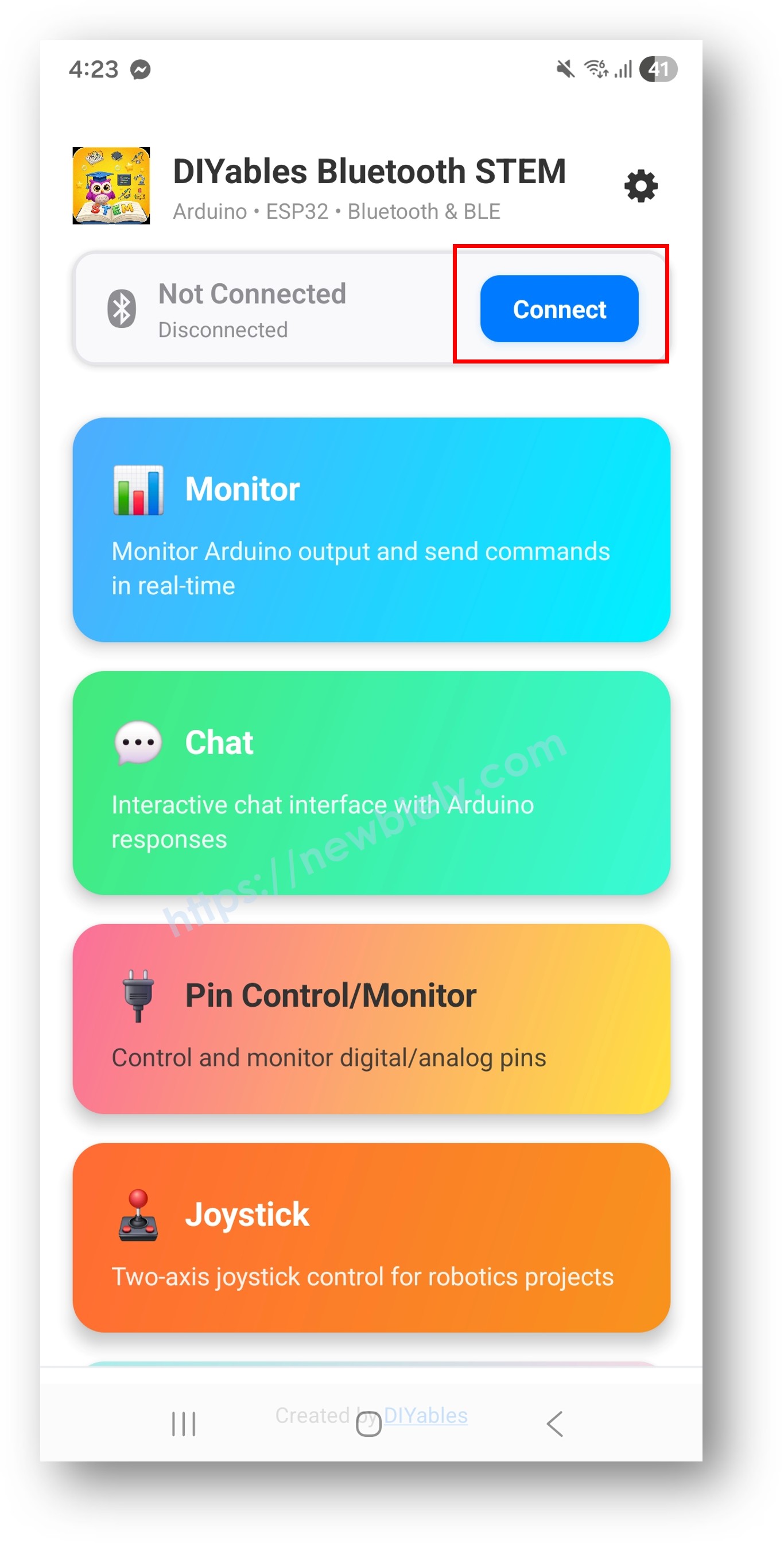
Assurez-vous que le Bluetooth est activé sur votre téléphone
Sur l'écran d'accueil, appuyez sur le bouton Connect. L'application va scanner à la fois les appareils BLE et Bluetooth Classique.
Trouvez et appuyez sur votre appareil dans les résultats de scan pour vous connecter :
Pour Bluetooth Classique : appuyez sur "ESP32_Pins"
Pour BLE : appuyez sur "ESP32BLE_Pins"
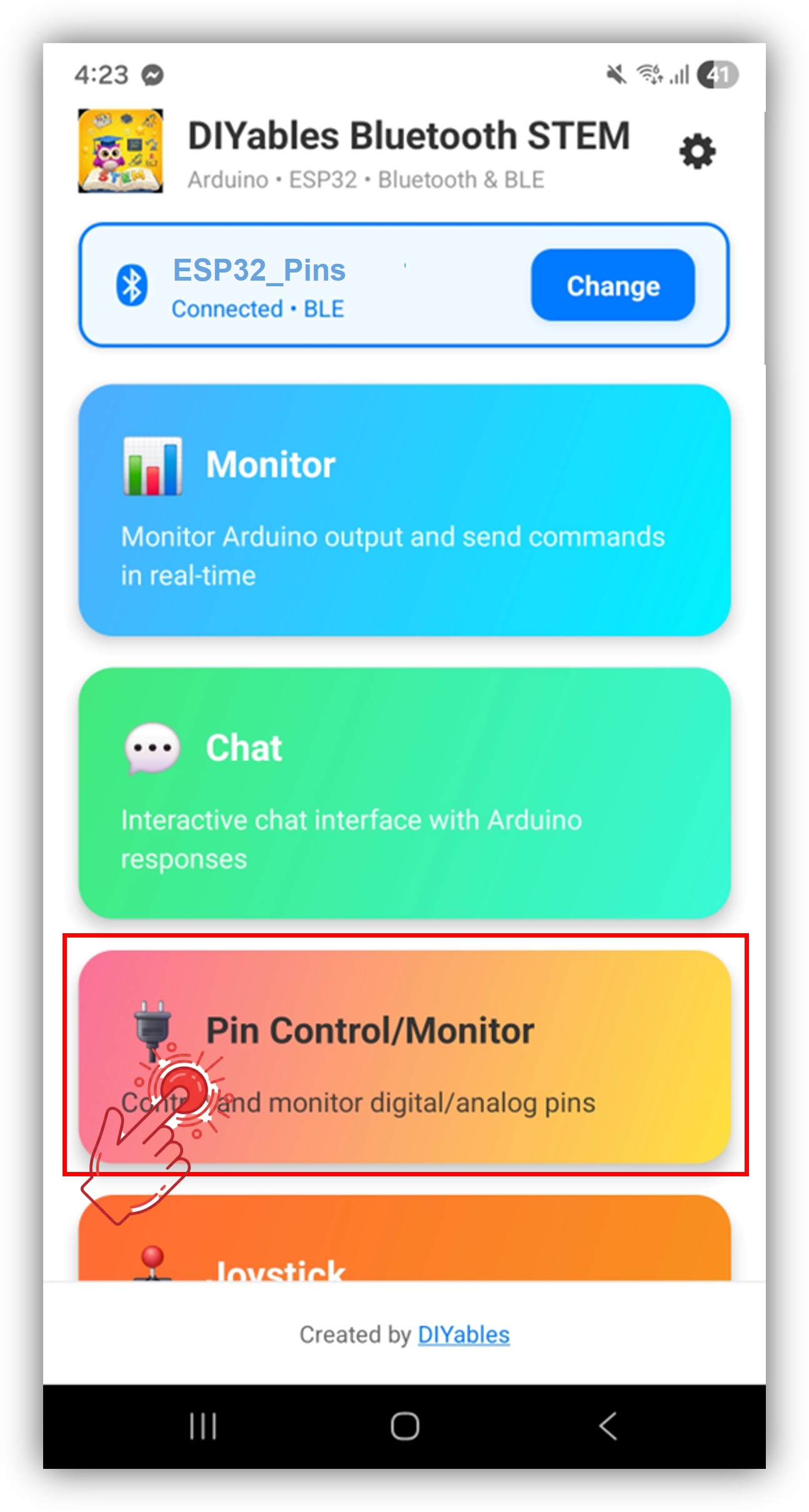
Une fois connecté, l'application retourne automatiquement à l'écran d'accueil. Sélectionnez l'application Digital Pins dans le menu des applications.
Note : Vous pouvez appuyer sur l'icône des paramètres sur l'écran d'accueil pour masquer/afficher les applications sur l'écran d'accueil. Pour plus de détails, voir le Manuel d'Utilisation DIYables Bluetooth App.
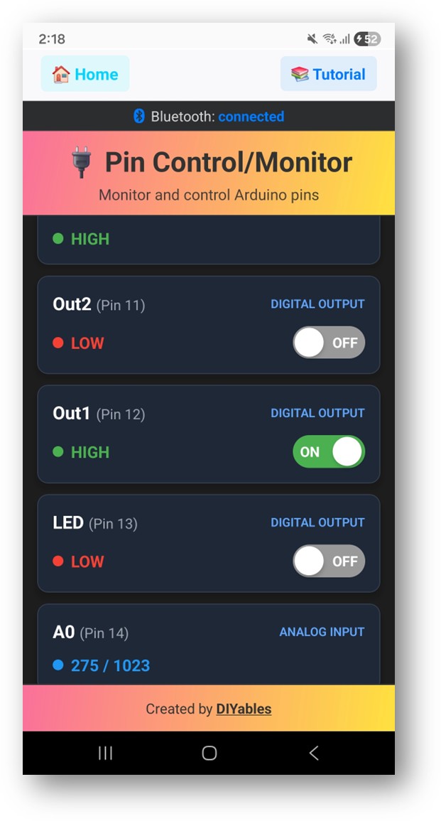
Basculez les broches de sortie en appuyant dessus, et regardez les broches d'entrée se mettre à jour en temps réel
Maintenant regardez de nouveau le Moniteur Série dans l'Arduino IDE. Vous verrez :
Newbiely | Arduino IDE 2.3.8
──
☐
✕
File
Edit
Sketch
Tools
Help
ESP32 Dev Module
Newbiely.ino
···
8Serial.println("Hello World!");
Output
Serial Monitor
Message (Enter to send message to 'ESP32 Dev Module' on 'COM15')
New Line
9600 baud
Bluetooth connected!
Pin 2 set to HIGH
Pin 16 set to LOW
Input pin 18 changed to LOW
Analog pin 34 changed to 2048
Ln 11, Col 1
ESP32 Dev Module on COM15
2
Basculez les broches dans l'application et regardez le retour en temps réel dans le Moniteur Série
Personnalisation Créative - Adaptez le Code à Votre Projet
Configurer les Broches
Activez les broches avec des noms personnalisés et des modes :
// Activer des broches individuelles avec mode et nom personnalisébluetoothPins.enablePin(2, BT_PIN_OUTPUT, "LED"); // LED intégréebluetoothPins.enablePin(16, BT_PIN_OUTPUT, "Relay1"); // Contrôle relaisbluetoothPins.enablePin(17, BT_PIN_OUTPUT, "Relay2"); // Contrôle relaisbluetoothPins.enablePin(18, BT_PIN_INPUT, "Button"); // Entrée boutonbluetoothPins.enablePin(34, BT_PIN_INPUT, "Sensor"); // Capteur analogique// Désactiver une broche spécifiquebluetoothPins.disablePin(17);// Vérifier le statut d'une brochebool isEnabled = bluetoothPins.isPinEnabled(2);int mode = bluetoothPins.getPinMode(2);int count = bluetoothPins.getEnabledPinCount();
Gérer les Commandes d'Écriture de Broche
Utilisez le callback onPinWrite() pour contrôler le matériel lorsque l'application bascule une broche :
bluetoothPins.onPinWrite([](int pin, int state) {digitalWrite(pin, state);Serial.print("Pin ");Serial.print(pin);Serial.print(" set to ");Serial.println(state ? "HIGH" : "LOW");});
Gérer les Commandes de Lecture de Broche
Utilisez le callback onPinRead() pour retourner les états des broches à l'application :
bluetoothPins.onPinRead([](int pin) -> int {if (pin == 34 || pin == 35) {// Lire la valeur analogique pour les broches ADCreturnanalogRead(pin); } else {// Lire la valeur numérique pour les autres brochesreturndigitalRead(pin); }});
Gérer les Changements de Mode de Broche
Utilisez le callback onPinModeChange() pour changer dynamiquement les modes de broche :
Envoyer des Mises à Jour d'État de Broche en Temps Réel
Poussez les changements d'état de broche vers l'application depuis votre code :
// Détecter les changements d'entrée et envoyer les mises à jourint currentState = digitalRead(18);if (currentState != lastState) { lastState = currentState; bluetoothPins.updatePinState(18, currentState);}// Envoyer les mises à jour de valeur analogiqueint analogValue = analogRead(34);if (abs(analogValue - lastAnalogValue) > 50) { lastAnalogValue = analogValue; bluetoothPins.updatePinState(34, analogValue);}
Gérer les Événements de Connexion
bluetoothServer.setOnConnected([]() {Serial.println("Bluetooth connected!");});bluetoothServer.setOnDisconnected([]() {Serial.println("Bluetooth disconnected!");// Sécurité : éteindre toutes les sorties lors de la déconnexiondigitalWrite(2, LOW);digitalWrite(16, LOW);digitalWrite(17, LOW);});
Comment Utiliser les Broches Numériques
Contrôles de l'Interface de l'Application
L'interface des broches numériques dans l'Application DIYables Bluetooth fournit :
Liste des Broches : Affiche toutes les broches activées avec noms et états actuels
Boutons de Basculement : Appuyez sur les broches de sortie pour basculer HIGH/LOW
Affichage d'Entrée : Affichage en temps réel des états des broches d'entrée
Valeurs Analogiques : Affiche les valeurs analogiques brutes pour les broches ADC
Modes de Broche
BT_PIN_OUTPUT (0) : Contrôle la sortie numérique — bascule depuis l'application
constint BUTTON_PINS[] = {18, 19, 21, 22};const char* BUTTON_NAMES[] = {"Btn1", "Btn2", "Btn3", "Btn4"};constint NUM_BUTTONS = 4;int lastButtonStates[4] = {HIGH, HIGH, HIGH, HIGH};voidsetup() {for (int i = 0; i < NUM_BUTTONS; i++) {pinMode(BUTTON_PINS[i], INPUT_PULLUP); bluetoothPins.enablePin(BUTTON_PINS[i], BT_PIN_INPUT, BUTTON_NAMES[i]); } bluetoothPins.onPinRead([](int pin) -> int {returndigitalRead(pin); });}voidloop() { bluetoothServer.loop();// Vérifier les changements d'état des boutonsfor (int i = 0; i < NUM_BUTTONS; i++) {int state = digitalRead(BUTTON_PINS[i]);if (state != lastButtonStates[i]) { lastButtonStates[i] = state; bluetoothPins.updatePinState(BUTTON_PINS[i], state); } }delay(10);}
Système Mixte Entrée/Sortie
voidsetup() {// Broches de sortie pour les actionneurs bluetoothPins.enablePin(2, BT_PIN_OUTPUT, "LED"); bluetoothPins.enablePin(16, BT_PIN_OUTPUT, "Relay");// Broches d'entrée numériques pour les capteurs bluetoothPins.enablePin(18, BT_PIN_INPUT, "Motion"); bluetoothPins.enablePin(19, BT_PIN_INPUT, "Door");// Broches d'entrée analogiques pour les capteurs bluetoothPins.enablePin(34, BT_PIN_INPUT, "Light"); bluetoothPins.enablePin(35, BT_PIN_INPUT, "Temp");// Configurer le matérielpinMode(2, OUTPUT);pinMode(16, OUTPUT);pinMode(18, INPUT_PULLUP);pinMode(19, INPUT_PULLUP); bluetoothPins.onPinWrite([](int pin, int state) {digitalWrite(pin, state); }); bluetoothPins.onPinRead([](int pin) -> int {if (pin == 34 || pin == 35) returnanalogRead(pin);returndigitalRead(pin); });}
Techniques de Programmation Avancées
Verrouillage de Sécurité
bool safetyEnabled = true;bluetoothPins.onPinWrite([](int pin, int state) {// Vérification de sécurité : ne pas permettre les sorties conflictuellesif (pin == 16 && state == HIGH) {// Vérifier si le verrouillage de sécurité permet ceciif (digitalRead(18) == LOW) { // Le commutateur de sécurité doit être engagé bluetoothPins.updatePinState(16, 0); // Rejeter la commandeSerial.println("SAFETY: Operation blocked - safety switch off");return; } }digitalWrite(pin, state);});
Utilisez les broches numériques pour on/off et les sliders pour l'intensité PWM :
bluetoothPins.onPinWrite([](int pin, int state) {if (state == HIGH) {// Quand la broche est activée, appliquer le PWM contrôlé par slideranalogWrite(pin, map(currentSlider1, 0, 100, 0, 255)); } else {analogWrite(pin, 0); }});
Combiner avec Bluetooth Monitor
Enregistrez les changements de broches dans le moniteur :
N'hésitez pas à partager le lien de ce tutoriel. Cependant, veuillez ne pas utiliser notre contenu sur d'autres sites web. Nous avons investi beaucoup d'efforts et de temps pour créer ce contenu, veuillez respecter notre travail !