ESP32 - Moteur servo à encodeur rotatif

Dans ce tutoriel, nous allons apprendre à programmer l'ESP32 et l'encodeur rotatif pour contrôler l'angle du moteur servo.

Préparation du matériel

1×ESP-WROOM-32 Dev Module
1×USB Cable Type-C
1×Servo Motor
1×Rotary Encoder
1×Breadboard
1×Jumper Wires
1×(Recommended) ESP32 Screw Terminal Adapter

Or you can buy the following sensor kits:

1×DIYables Sensor Kit (30 sensors/displays)
1×DIYables Sensor Kit (18 sensors/displays)
Divulgation : Certains des liens fournis dans cette section sont des liens affiliés Amazon. Nous pouvons recevoir une commission pour tout achat effectué via ces liens, sans coût supplémentaire pour vous. Nous vous remercions de votre soutien.

À propos du moteur servo et de l'encodeur rotatif

Vous ne connaissez pas le moteur servo et le codeur rotatif, y compris leurs brochages, fonctionnalités et programmation ? Explorez des tutoriels complets sur ces sujets ci-dessous :

Diagramme de câblage
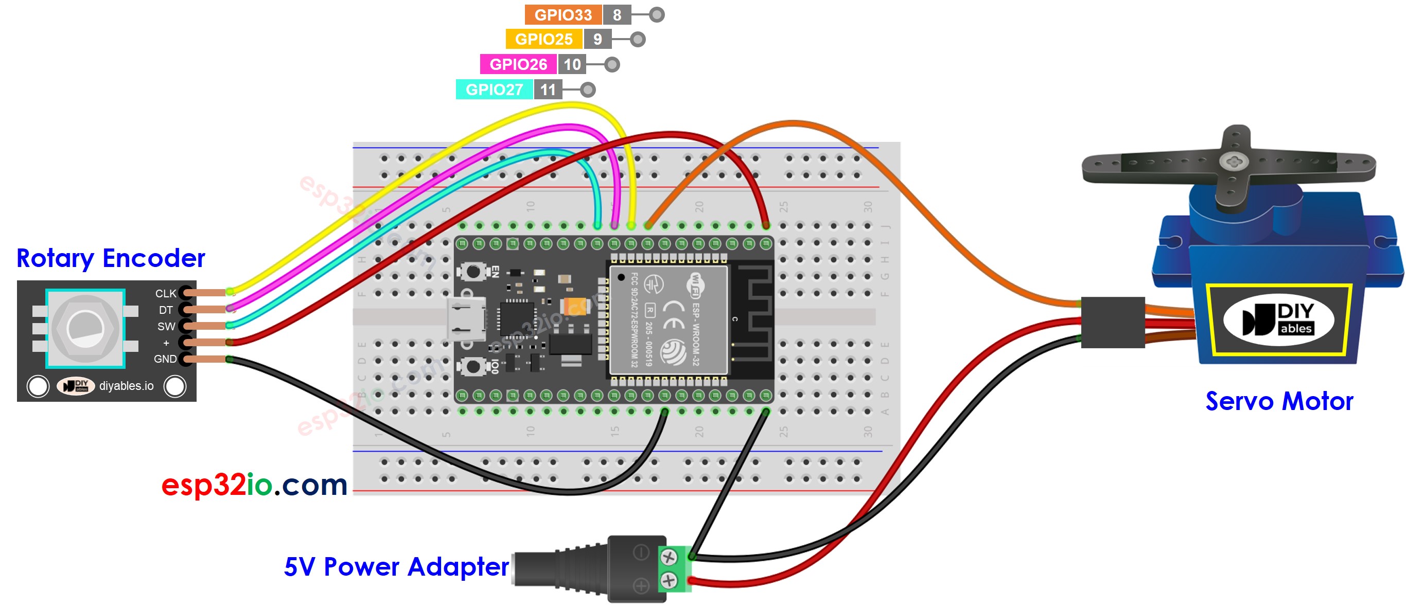
Schéma de câblage du moteur servo et encodeur rotatif ESP32

This image is created using Fritzing. Click to enlarge image

Si vous ne savez pas comment alimenter l'ESP32 et d'autres composants, vous pouvez trouver des conseils dans le tutoriel suivant : Comment alimenter l'ESP32.

Code ESP32

/* * Ce code ESP32 a été développé par newbiely.fr * Ce code ESP32 est mis à disposition du public sans aucune restriction. * Pour des instructions complètes et des schémas de câblage, veuillez visiter: * https://newbiely.fr/tutorials/esp32/esp32-rotary-encoder-servo-motor */ #include <Servo.h> #define CLK_PIN 25 // ESP32 pin GPIO25 connected to the rotary encoder's CLK pin #define DT_PIN 26 // ESP32 pin GPIO26 connected to the rotary encoder's DT pin #define SW_PIN 27 // ESP32 pin GPIO27 connected to the rotary encoder's SW pin #define SERVO_PIN 33 // ESP32 pin GPIO33 connected to the servo motor #define DIRECTION_CW 0 // clockwise direction #define DIRECTION_CCW 1 // counter-clockwise direction int counter = 0; int direction = DIRECTION_CW; int CLK_state; int prev_CLK_state; int angle = 90; Servo servo; // create servo object to control a servo void setup() { Serial.begin(9600); // configure encoder pins as inputs pinMode(CLK_PIN, INPUT); pinMode(DT_PIN, INPUT); // read the initial state of the rotary encoder's CLK pin prev_CLK_state = digitalRead(CLK_PIN); servo.attach(SERVO_PIN); // attaches the servo on pin 9 to the servo object servo.write(angle); } void loop() { // read the current state of the rotary encoder's CLK pin CLK_state = digitalRead(CLK_PIN); // If the state of CLK is changed, then pulse occurred // React to only the rising edge (from LOW to HIGH) to avoid double count if (CLK_state != prev_CLK_state && CLK_state == HIGH) { // if the DT state is HIGH // the encoder is rotating in counter-clockwise direction => decrease the counter if (digitalRead(DT_PIN) == HIGH) { direction = DIRECTION_CCW; counter--; angle -= 2; // you can change this resolution } else { // the encoder is rotating in clockwise direction => increase the counter direction = DIRECTION_CW; counter++; angle += 2; // you can change this resolution } if (angle < 0) angle = 0; else if (angle > 180) angle = 180; // sets the servo angle according to the counter servo.write(angle); Serial.print("COUNTER: "); Serial.print(counter); Serial.print(" | ANGLE: "); Serial.println(angle); } // save last CLK state prev_CLK_state = CLK_state; }

Étapes rapides

  • Si c'est la première fois que vous utilisez un ESP32, consultez comment configurer l'environnement pour ESP32 sur Arduino IDE.
  • Réalisez le câblage comme sur l'image ci-dessus.
  • Connectez le tableau ESP32 à votre PC via un câble micro USB.
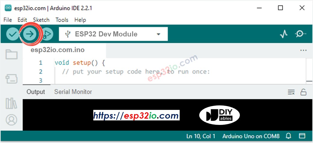
  • Ouvrez Arduino IDE sur votre PC.
  • Sélectionnez la bonne carte ESP32 (par exemple ESP32 Dev Module) et le port COM.
  • Connectez l'ESP32 au PC via un câble USB.
  • Ouvrez Arduino IDE, sélectionnez la bonne carte et le port.
  • Copiez le code ci-dessus et ouvrez-le avec Arduino IDE.
  • Cliquez sur le bouton Upload sur Arduino IDE pour télécharger le code sur ESP32.
Téléversement de code Arduino IDE
  • Ouvrez le moniteur série
  • Tournez l'encodeur rotatif
  • Observez la rotation du moteur servo
  • Consultez le résultat sur le moniteur série
COM6
Send
COUNTER: 0 | ANGLE: 90 COUNTER: 1 | ANGLE: 92 COUNTER: 2 | ANGLE: 94 COUNTER: 3 | ANGLE: 96 COUNTER: 4 | ANGLE: 98 COUNTER: 5 | ANGLE: 100 COUNTER: 6 | ANGLE: 102
Autoscroll Show timestamp
Clear output
9600 baud  
Newline  

Explication du code

Lisez l'explication ligne par ligne dans les lignes de commentaire du code source !

Vidéo

※ OUR MESSAGES

  • Please feel free to share the link of this tutorial. However, Please do not use our content on any other websites. We invested a lot of effort and time to create the content, please respect our work!