Arduino Uno R4 - Interface SPI ILI9341 ILI9488 ST7789 Écran TFT LCD Tactile

L'Arduino Uno R4 — disponible en versions Minima et WiFi — apporte un processeur Renesas RA4M1 à 48 MHz et plus de SRAM que l'Uno classique, tout en conservant le même format de connecteur. Les broches SPI matérielles sont aux mêmes emplacements physiques, donc tout câblage TFT qui fonctionne sur l'Uno R3 fonctionne directement sur l'Uno R4 sans aucune modification.

Dans ce guide, vous allez :

Ce guide couvre les écrans TFT LCD SPI tactiles et non tactiles. Il fonctionne avec les panneaux de 1,3, 1,54, 2,2, 2,4, 2,8, 3,2 et 3,5 pouces pilotés par les puces ILI9341, ILI9488 ou ST7789.
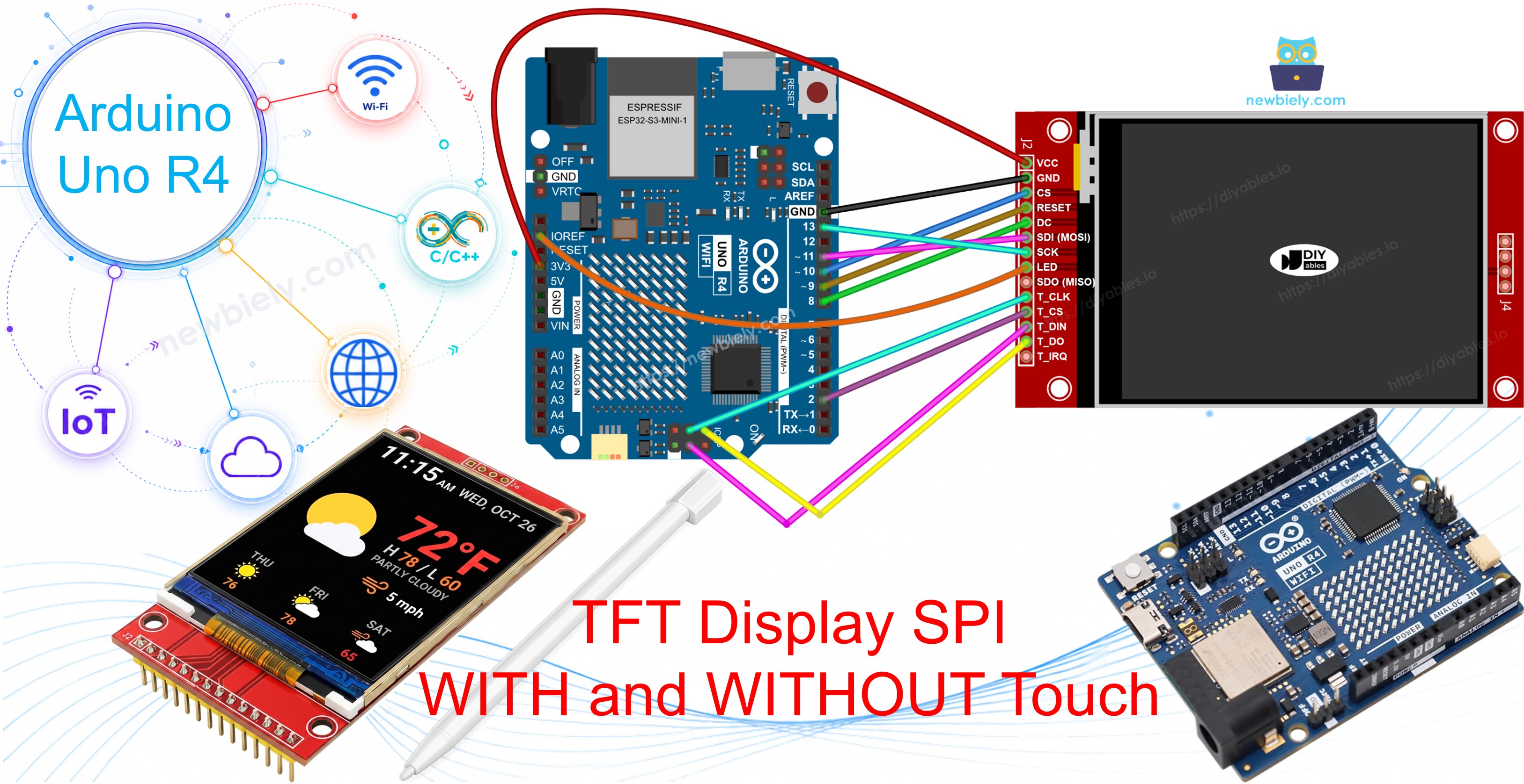
Arduino Uno R4 TFT SPI Display

Conseil — alternative plus simple et plus rapide : Si vous utilisez un Arduino Uno R4, envisagez le TFT Touch Shield à la place. Il se branche directement sur le connecteur Uno R4 — aucun fil de liaison ni convertisseur de niveau requis. Il utilise une interface parallèle 8 bits, qui transfère les données de pixels nettement plus rapidement que SPI.

Aperçu de l'Écran TFT SPI

Un écran TFT SPI est un panneau LCD couleur piloté par une puce contrôleur via le bus SPI. La bibliothèque DIYables_TFT_SPI prend en charge trois puces pilotes courantes :

  • ILI9341 — couleur RGB565 16 bits, jusqu'à 40 MHz SPI.
  • ILI9488 — couleur RGB666 18 bits, jusqu'à 24 MHz SPI.
  • ST7789 — couleur RGB565 16 bits, jusqu'à 40 MHz SPI.

Recommandation : Si vous n'avez pas encore acheté d'écran, nous recommandons le pilote ST7789. Il est largement disponible, fonctionne à pleine vitesse SPI 40 MHz et est le choix le plus simple pour les nouveaux projets.

La bibliothèque étend Adafruit GFX, donc toutes les fonctions de dessin et de texte standard sont disponibles.

Brochage

La plupart des modules d'écran TFT LCD SPI ont les broches suivantes :

Broches d'affichage :

Pin Function
VCC Power supply
GND Ground
CS Chip Select — pulled low to select the display on the SPI bus
DC / RS Data / Command select — high for pixel data, low for commands
RST Hardware reset — optional; tie to 3.3V if unused
MOSI / SDI / SDA SPI data in (MCU → display)
SCK / CLK SPI clock
MISO / SDO SPI data out (display → MCU) — optional for display-only use
LED / BL / BLK Backlight power — connect to 3.3V or a PWM pin for dimming

Broches de la carte SD (si votre application a besoin d'accéder à la carte SD) :

Pin Function
SD_CS / TF_CS SD card Chip Select
MOSI / SDI MOSI — data from MCU to SD card
SCK / CLK SCK — SPI clock
MISO / SDO MISO — data from SD card to MCU

Pour les écrans TFT qui prennent en charge le tactile, il y a des broches tactiles supplémentaires (si votre application utilise la fonction tactile et si l'écran la prend en charge) :

Pin Function
T_CS Touch controller Chip Select
T_CLK SCK — SPI clock
T_DIN MOSI — data from MCU to touch controller
T_DO MISO — data from touch controller to MCU
T_IRQ Touch interrupt — optional; signals when the screen is being touched

Remarque : Certains modules d'affichage non tactiles exposent également les broches T_CS, T_CLK, T_DIN, T_DO et T_IRQ. Celles-ci sont non fonctionnelles sur ces cartes — le circuit intégré du contrôleur tactile n'est pas monté. Elles apparaissent parce que le PCB réutilise la même conception que la version tactile pour réduire les variantes de fabrication.
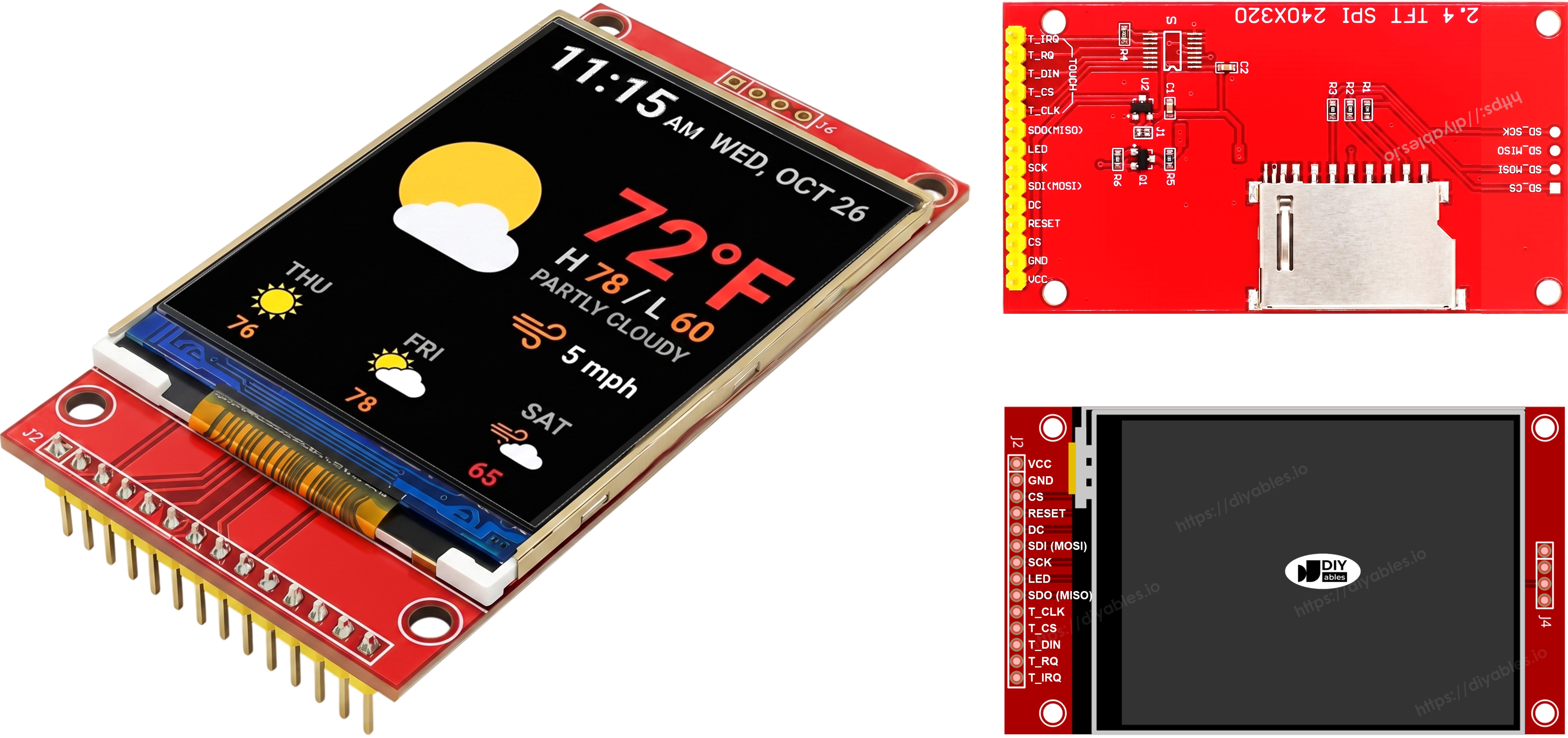
TFT SPI Display Pinout

Schéma de Câblage

⚠ Important — incompatibilité de tension : L'Arduino Uno R4 est une carte 5V. Ses broches GPIO délivrent une logique 5V, mais les écrans TFT SPI fonctionnent à 3,3V. Connecter les lignes de signal (MOSI, SCK, CS, DC, RST et T_CS si vous utilisez le tactile) directement de l'Uno R4 à l'écran endommagera l'écran. Vous devez utiliser un Convertisseur de Niveau 5V vers 3,3V sur chaque ligne de signal piloté par le MCU entre l'Uno R4 et l'écran. La ligne MISO (écran → MCU) n'a pas besoin de convertisseur de niveau. Un seul module 4 canaux suffit pour le câblage sans tactile ; le câblage avec tactile nécessite 6 canaux au total (ajouter T_CS), donc utilisez deux modules 4 canaux ou un module 8 canaux. Connectez le VCC du TFT à la broche 3,3V de l'Uno R4.

Sans Tactile

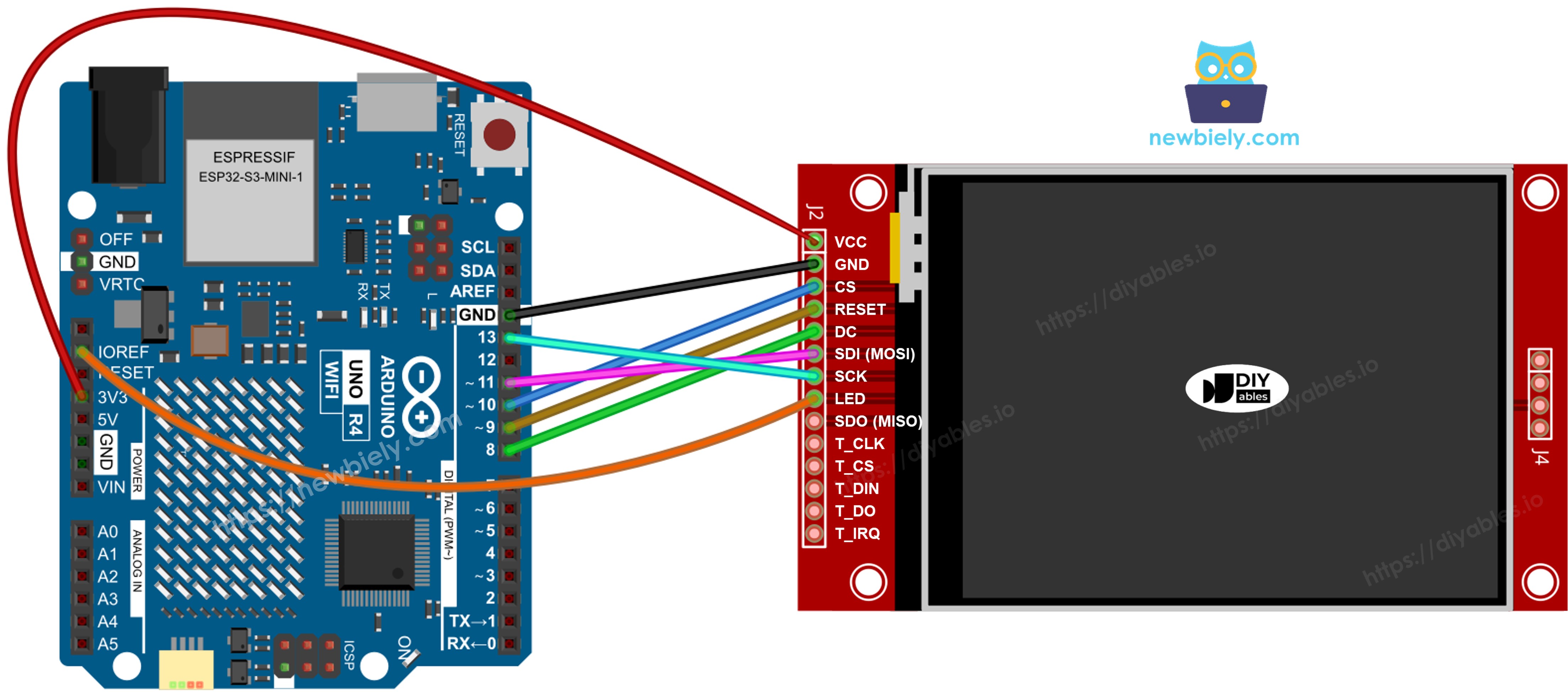
Connectez MOSI à D11, SCK à D13, MISO à D12 sur l'Uno R4. CS, DC et RST peuvent être n'importe quel GPIO disponible — D10, D9, D8 sont utilisés dans les exemples.

Affichage :

TFT Pin Arduino Uno R4 Pin Description
VCC 3.3V or 5V Power supply
GND GND Ground
CS D10 Chip Select
DC / RS D9 Data / Command select
RST D8 Reset (optional)
MOSI / SDI D11 Hardware SPI MOSI
SCK D13 Hardware SPI clock
MISO / SDO D12 Hardware SPI MISO (optional)
LED / BL 3.3V Backlight power

Carte SD (si votre application a besoin d'accéder à la carte SD) :

SD Pin Arduino Uno R4 Pin Description
SD_CS / TF_CS any free GPIO SD card Chip Select
MOSI / SDI D11 Shared with display MOSI (D11)
SCK / CLK D13 Shared with display SCK (D13)
MISO / SDO D12 Shared with display MISO (D12)
Arduino Uno R4 TFT SPI Display wiring diagram without touch

Cette image a été créée avec Fritzing. Cliquez pour agrandir l'image.

Avec Tactile

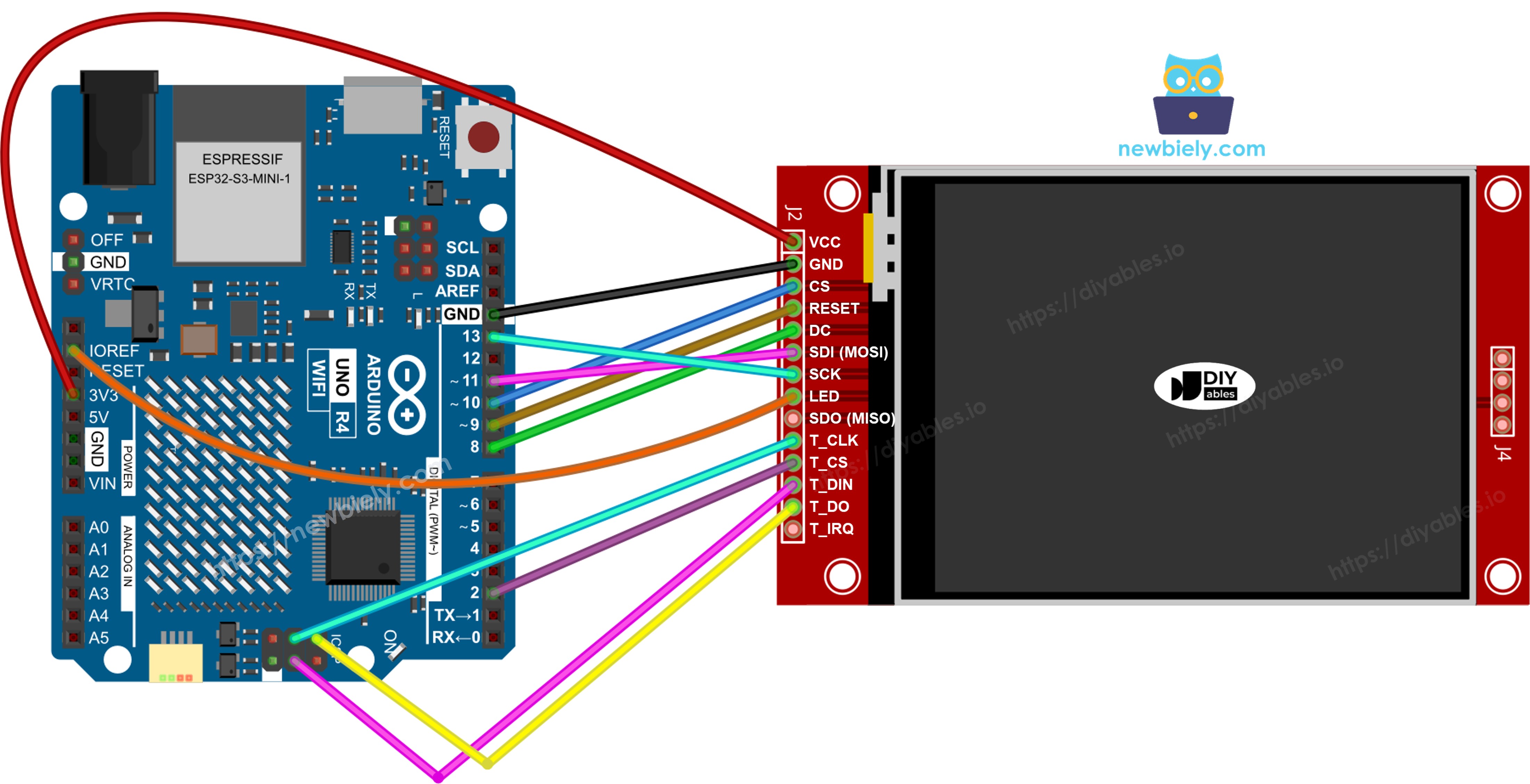
Connectez le contrôleur tactile XPT2046 au bus SPI de l'Arduino Uno R4, partageant D11, D13 et D12 avec l'affichage.

Affichage :

TFT Pin Arduino Uno R4 Pin Description
VCC 3.3V or 5V Power supply
GND GND Ground
CS D10 Chip Select
DC / RS D9 Data / Command select
RST D8 Reset (optional)
MOSI / SDI D11 Hardware SPI MOSI
SCK D13 Hardware SPI clock
MISO / SDO D12 Hardware SPI MISO (optional)
LED / BL 3.3V Backlight power

Contrôleur tactile (si votre application utilise la fonction tactile et si l'écran la prend en charge) :

Touch Pin Arduino Uno R4 Pin Description
T_CS any free GPIO Touch Chip Select
T_IRQ any free GPIO Touch interrupt (optional)
T_DIN D11 Shared with display MOSI (D11)
T_CLK D13 Shared with display SCK (D13)
T_DO D12 Shared with display MISO (D12)
Arduino Uno R4 TFT SPI Display wiring diagram with touch

Cette image a été créée avec Fritzing. Cliquez pour agrandir l'image.

Voir Comment alimenter l'Arduino UNO R4..

Si votre MCU dispose de deux interfaces SPI matérielles ou plus, vous pouvez assigner chaque périphérique (affichage, carte SD, contrôleur tactile) à son propre bus SPI dédié. Si votre MCU n'a qu'une seule interface SPI matérielle, les trois périphériques partagent les mêmes trois lignes de données (MOSI, SCK, MISO) — sur l'Uno R4 ce sont D11, D13 et D12. Chaque périphérique a sa propre broche CS, donc un seul est actif à la fois. La bibliothèque DIYables_TFT_SPI gère à la fois l'affichage et le contrôleur tactile XPT2046 via une seule API — aucune bibliothèque SPI séparée n'est nécessaire pour le côté tactile.

Comment Installer la Bibliothèque

  1. Branchez l'Arduino Uno R4 à votre ordinateur avec un câble USB Type-C.
  2. Dans l'Arduino IDE, vérifiez que la bonne carte (Arduino Uno R4 Minima ou WiFi) et le bon port série sont sélectionnés.
  3. Cliquez sur l'icône Bibliothèques dans la barre latérale gauche.
  4. Tapez "DIYables_TFT_SPI" dans la zone de recherche et localisez la bibliothèque publiée par DIYables.
  5. Cliquez sur Installer pour ajouter la bibliothèque. Lorsqu'on vous le demande, installez également la dépendance Adafruit GFX Library.
  • Search for DIYables TFT SPI created by DIYables.io and click the Install button.
Newbiely | Arduino IDE 2.3.8
──
File
Edit
Sketch
Tools
Help
Arduino Uno R4 WiFi
Library Manager
Type:
All
Topic:
All
DIYables TFT SPI by DIYables.io
Works with both touch and non-touch versions of the same SPI TFT modules. Supports ILI9341 (240x320, 16-bit RGB565), ILI9488 (320x480, 18-bit RGB666), and ST7789 (240x320, 16-bit RGB565) displays over SPI. Includes built-in driver for XPT2046 / HR2046 / ADS7843 SPI touch controllers and 4-wire resistive touch panels - no separate touch library required. Use the display-only API for non-touch panels, or add initTouchSPI() to enable touch on modules that include a touch controller. Extends Adafruit GFX for full graphics support. Works with any Arduino-compatible board that has SPI. More info
1.0.3
INSTALL
Newbiely.ino
···
1 void setup() {
Output
Serial Monitor
Ln 1, Col 1
Arduino Uno R4 WiFi on COM15
1

Structure Minimale du Sketch

Tous les sketches utilisant la bibliothèque DIYables_TFT_SPI partagent ce squelette :

#include <DIYables_TFT_SPI.h> #define TFT_CS_PIN 10 #define TFT_DC_PIN 9 #define TFT_RST_PIN 8 // Uncomment the line that matches your driver chip: // DIYables_ILI9341_SPI TFT_display(240, 320, TFT_CS_PIN, TFT_DC_PIN, TFT_RST_PIN); // DIYables_ILI9488_SPI TFT_display(320, 480, TFT_CS_PIN, TFT_DC_PIN, TFT_RST_PIN); DIYables_ST7789_SPI TFT_display(240, 320, TFT_CS_PIN, TFT_DC_PIN, TFT_RST_PIN); void setup() { TFT_display.begin(); TFT_display.setRotation(1); } void loop() { // drawing code here }

Passez les dimensions physiques en pixels de votre panneau au constructeur. Les modules avec la même puce pilote existent en différentes tailles.

Dessiner des Formes

L'exemple DrawShapes montre les primitives de dessin Adafruit GFX : cercles, triangles, rectangles, rectangles arrondis et lignes.

/* * Ce code Arduino UNO R4 a été développé par newbiely.fr * Ce code Arduino UNO R4 est mis à disposition du public sans aucune restriction. * Pour des instructions complètes et des schémas de câblage, veuillez visiter: * https://newbiely.fr/tutorials/arduino-uno-r4/arduino-uno-r4-tft-lcd-touch-display-spi */ /* Created by DIYables This example code is in the public domain Product page: https://diyables.io */ // ============================================= // Single include brings in the base class plus all driver classes. // ============================================= #include <DIYables_TFT_SPI.h> // ============================================= // Wiring (Arduino Uno / Nano) // --------------------------------------------- // TFT module Arduino Uno / Nano // ------------ --------------------------------- // VCC -> 5V // GND -> GND // CS -> D10 (TFT_CS_PIN) // RESET -> D9 (TFT_RST_PIN) // DC / RS -> D8 (TFT_DC_PIN) // SDI / MOSI -> D11 (hardware SPI MOSI) // SCK -> D13 (hardware SPI SCK) // LED -> 3.3V (or any GPIO via initBacklight) // SDO / MISO -> D12 (only needed when reading from display) // ============================================= // ============================================= // SPI pin definitions (adjust for your board) // ============================================= #define TFT_CS_PIN 10 #define TFT_DC_PIN 8 #define TFT_RST_PIN 9 // Panel resolution in native (portrait) orientation - change to match your module #define TFT_WIDTH 240 #define TFT_HEIGHT 320 // MOSI and SCK use default hardware SPI pins // ============================================= // Create display object (uncomment matching driver) // ============================================= // DIYables_ILI9341_SPI TFT_display(TFT_WIDTH, TFT_HEIGHT, TFT_CS_PIN, TFT_DC_PIN, TFT_RST_PIN); // DIYables_ILI9488_SPI TFT_display(TFT_WIDTH, TFT_HEIGHT, TFT_CS_PIN, TFT_DC_PIN, TFT_RST_PIN); DIYables_ST7789_SPI TFT_display(TFT_WIDTH, TFT_HEIGHT, TFT_CS_PIN, TFT_DC_PIN, TFT_RST_PIN); #define BLACK DIYables_TFT_SPI::colorRGB(0, 0, 0) #define BLUE DIYables_TFT_SPI::colorRGB(0, 0, 255) #define RED DIYables_TFT_SPI::colorRGB(255, 0, 0) #define GREEN DIYables_TFT_SPI::colorRGB(0, 255, 0) #define ORANGE DIYables_TFT_SPI::colorRGB(255, 165, 0) #define PINK DIYables_TFT_SPI::colorRGB(255, 192, 203) #define VIOLET DIYables_TFT_SPI::colorRGB(148, 0, 211) #define TURQUOISE DIYables_TFT_SPI::colorRGB(64, 224, 208) #define WHITE DIYables_TFT_SPI::colorRGB(255, 255, 255) // Helper to draw a filled diamond void fillDiamond(int cx, int cy, int h, int v, uint16_t color) { int x0 = cx, y0 = cy - v; int x1 = cx + h, y1 = cy; int x2 = cx, y2 = cy + v; int x3 = cx - h, y3 = cy; TFT_display.fillTriangle(x0, y0, x1, y1, x2, y2, color); TFT_display.fillTriangle(x0, y0, x2, y2, x3, y3, color); } void setup() { TFT_display.begin(); TFT_display.setRotation(1); // Landscape } void loop() { TFT_display.fillScreen(WHITE); uint16_t w = TFT_display.width(); uint16_t h = TFT_display.height(); // Scale positions relative to screen size with better spacing int col1 = w / 8; int col2 = w * 3 / 8; int col3 = w * 5 / 8; int col4 = w * 7 / 8; int row1 = h / 4; int row2 = h / 2; int row3 = h * 3 / 4; // Outlined circle TFT_display.drawCircle(col1, row1, 30, RED); // Filled circle TFT_display.fillCircle(col2, row1, 30, RED); // Outlined triangle TFT_display.drawTriangle(col3 - 30, row1 + 25, col3 + 30, row1 + 25, col3, row1 - 25, BLUE); // Filled triangle TFT_display.fillTriangle(col4 - 30, row1 + 25, col4 + 30, row1 + 25, col4, row1 - 25, GREEN); // Outlined rectangle TFT_display.drawRect(col1 - 35, row2 - 20, 70, 40, ORANGE); // Filled rectangle TFT_display.fillRect(col2 - 35, row2 - 20, 70, 40, TURQUOISE); // Outlined round rectangle TFT_display.drawRoundRect(col3 - 35, row2 - 20, 70, 40, 10, VIOLET); // Filled round rectangle TFT_display.fillRoundRect(col4 - 35, row2 - 20, 70, 40, 10, PINK); // Outlined diamond (centered between col1 and col2) int diamond1_x = (col1 + col2) / 2; TFT_display.drawLine(diamond1_x, row3 - 30, diamond1_x + 25, row3, GREEN); TFT_display.drawLine(diamond1_x + 25, row3, diamond1_x, row3 + 30, GREEN); TFT_display.drawLine(diamond1_x, row3 + 30, diamond1_x - 25, row3, GREEN); TFT_display.drawLine(diamond1_x - 25, row3, diamond1_x, row3 - 30, GREEN); // Filled diamond (centered between col3 and col4) int diamond2_x = (col3 + col4) / 2; fillDiamond(diamond2_x, row3, 25, 30, BLUE); delay(10000); }

Comment Exécuter

  • Câblez le module TFT à l'Arduino Uno R4 comme indiqué dans le schéma de câblage.
  • Branchez le câble USB Type-C.
  • Collez le code dans l'Arduino IDE, choisissez la bonne carte et le bon port, et appuyez sur Téléverser.
  • L'écran affiche une grille de formes colorées qui se rafraîchit toutes les quelques secondes.

Référence Rapide des Méthodes

Method What It Does Usage
begin() Initialize the display controller. Call once in setup(). TFT_display.begin();
setRotation(r) Rotate the coordinate system. 0=portrait, 1=landscape. TFT_display.setRotation(1);
fillScreen(color) Clear screen with a solid color. TFT_display.fillScreen(WHITE);
colorRGB(r,g,b) Build a 16-bit RGB565 color from 8-bit components. colorRGB(0, 128, 255)
fillCircle(x,y,r,color) Draw a solid circle. TFT_display.fillCircle(80, 80, 40, RED);
fillRect(x,y,w,h,color) Draw a solid rectangle. TFT_display.fillRect(10, 10, 60, 40, BLUE);
drawRoundRect(x,y,w,h,r,color) Draw a rounded rectangle outline. TFT_display.drawRoundRect(5,5,100,50,10,GREEN);

Afficher du Texte et des Nombres

L'exemple ShowTextAndNumber montre comment afficher des chaînes et des nombres à différentes tailles, couleurs et positions.

/* * Ce code Arduino UNO R4 a été développé par newbiely.fr * Ce code Arduino UNO R4 est mis à disposition du public sans aucune restriction. * Pour des instructions complètes et des schémas de câblage, veuillez visiter: * https://newbiely.fr/tutorials/arduino-uno-r4/arduino-uno-r4-tft-lcd-touch-display-spi */ /* Created by DIYables This example code is in the public domain Product page: https://diyables.io */ // ============================================= // Single include brings in the base class plus all driver classes. // ============================================= #include <DIYables_TFT_SPI.h> // ============================================= // Wiring (Arduino Uno / Nano) // --------------------------------------------- // TFT module Arduino Uno / Nano // ------------ --------------------------------- // VCC -> 5V // GND -> GND // CS -> D10 (TFT_CS_PIN) // RESET -> D9 (TFT_RST_PIN) // DC / RS -> D8 (TFT_DC_PIN) // SDI / MOSI -> D11 (hardware SPI MOSI) // SCK -> D13 (hardware SPI SCK) // LED -> 3.3V (or any GPIO via initBacklight) // SDO / MISO -> D12 (only needed when reading from display) // ============================================= // ============================================= // SPI pin definitions (adjust for your board) // ============================================= #define TFT_CS_PIN 10 #define TFT_DC_PIN 8 #define TFT_RST_PIN 9 // Panel resolution in native (portrait) orientation - change to match your module #define TFT_WIDTH 240 #define TFT_HEIGHT 320 // ============================================= // Create display object (uncomment matching driver) // ============================================= // DIYables_ILI9341_SPI TFT_display(TFT_WIDTH, TFT_HEIGHT, TFT_CS_PIN, TFT_DC_PIN, TFT_RST_PIN); // DIYables_ILI9488_SPI TFT_display(TFT_WIDTH, TFT_HEIGHT, TFT_CS_PIN, TFT_DC_PIN, TFT_RST_PIN); DIYables_ST7789_SPI TFT_display(TFT_WIDTH, TFT_HEIGHT, TFT_CS_PIN, TFT_DC_PIN, TFT_RST_PIN); #define MAGENTA DIYables_TFT_SPI::colorRGB(255, 0, 255) #define WHITE DIYables_TFT_SPI::colorRGB(255, 255, 255) void setup() { Serial.begin(9600); Serial.println(F("TFT SPI Display - Show text and numbers")); TFT_display.begin(); TFT_display.setRotation(1); // Landscape TFT_display.fillScreen(WHITE); // Set text color and size TFT_display.setTextColor(MAGENTA); TFT_display.setTextSize(3); // Sample values float temperature = 23.5; float humidity = 78.6; // Display temperature TFT_display.setCursor(20, 20); TFT_display.print("Temperature: "); TFT_display.print(temperature, 1); TFT_display.print(char(247)); TFT_display.println("C"); // Display humidity TFT_display.setCursor(20, 60); TFT_display.print("Humidity: "); TFT_display.print(humidity, 1); TFT_display.print("%"); } void loop() { }

Comment Exécuter

  • Câblez et téléversez comme ci-dessus.
  • L'écran affiche plusieurs lignes de texte et de valeurs numériques.

Référence Rapide des Méthodes

Method What It Does Usage
setTextColor(color) Set text foreground color. TFT_display.setTextColor(BLACK);
setTextSize(size) Scale text. Size 1 is 6x8 pixels. TFT_display.setTextSize(2);
setCursor(x, y) Position the text cursor. TFT_display.setCursor(10, 30);
print(value) Print a string or number at the cursor. TFT_display.print("Temp: ");
println(value) Print and advance to next line. TFT_display.println(25.4);

Afficher une Image

L'exemple DrawImage affiche un bitmap couleur RGB565 stocké en mémoire programme. Les données d'image sont déclarées dans bitmap.h sous forme de tableau const uint16_t marqué PROGMEM. Cela conserve les données de pixels dans la flash plutôt que dans la SRAM, donc l'affichage fonctionne correctement même sur les cartes à RAM limitée. Copiez bitmap.h dans le dossier du sketch avant la compilation.

/* * Ce code Arduino UNO R4 a été développé par newbiely.fr * Ce code Arduino UNO R4 est mis à disposition du public sans aucune restriction. * Pour des instructions complètes et des schémas de câblage, veuillez visiter: * https://newbiely.fr/tutorials/arduino-uno-r4/arduino-uno-r4-tft-lcd-touch-display-spi */ /* Created by DIYables This example code is in the public domain Product page: https://diyables.io */ // ============================================= // Single include brings in the base class plus all driver classes. // ============================================= #include <DIYables_TFT_SPI.h> #include "bitmap.h" // ============================================= // Wiring (Arduino Uno / Nano) // --------------------------------------------- // TFT module Arduino Uno / Nano // ------------ --------------------------------- // VCC -> 5V // GND -> GND // CS -> D10 (TFT_CS_PIN) // RESET -> D9 (TFT_RST_PIN) // DC / RS -> D8 (TFT_DC_PIN) // SDI / MOSI -> D11 (hardware SPI MOSI) // SCK -> D13 (hardware SPI SCK) // LED -> 3.3V (or any GPIO via initBacklight) // SDO / MISO -> D12 (only needed when reading from display) // ============================================= // ============================================= // SPI pin definitions (adjust for your board) // ============================================= #define TFT_CS_PIN 10 #define TFT_DC_PIN 8 #define TFT_RST_PIN 9 // Panel resolution in native (portrait) orientation - change to match your module #define TFT_WIDTH 240 #define TFT_HEIGHT 320 // ============================================= // Create display object (uncomment matching driver) // ============================================= // DIYables_ILI9341_SPI TFT_display(TFT_WIDTH, TFT_HEIGHT, TFT_CS_PIN, TFT_DC_PIN, TFT_RST_PIN); // DIYables_ILI9488_SPI TFT_display(TFT_WIDTH, TFT_HEIGHT, TFT_CS_PIN, TFT_DC_PIN, TFT_RST_PIN); DIYables_ST7789_SPI TFT_display(TFT_WIDTH, TFT_HEIGHT, TFT_CS_PIN, TFT_DC_PIN, TFT_RST_PIN); #define WHITE DIYables_TFT_SPI::colorRGB(255, 255, 255) int img_width = 120; int img_height = 53; void setup() { Serial.begin(9600); Serial.println(F("TFT SPI Display - Draw Image")); TFT_display.begin(); uint16_t SCREEN_WIDTH = TFT_display.width(); uint16_t SCREEN_HEIGHT = TFT_display.height(); int x = (SCREEN_WIDTH - img_width) / 2; int y = (SCREEN_HEIGHT - img_height) / 2; TFT_display.fillScreen(WHITE); TFT_display.drawRGBBitmap(x, y, myBitmap, img_width, img_height); } void loop() { delay(2000); TFT_display.invertDisplay(true); delay(2000); TFT_display.invertDisplay(false); }

Comment Exécuter

  • Placez bitmap.h dans le même dossier que le fichier de sketch.
  • Câblez le module TFT à l'Arduino Uno R4 comme indiqué dans le schéma de câblage.
  • Branchez le câble USB Type-C.
  • Collez le code dans l'Arduino IDE, confirmez la carte et le port, et appuyez sur Téléverser.
  • L'écran affiche l'image bitmap chargée depuis la mémoire programme.

Référence Rapide des Méthodes

Method What It Does Usage
drawRGBBitmap(x,y,bitmap,w,h) Draw an RGB565 PROGMEM bitmap starting at pixel (x, y). TFT_display.drawRGBBitmap(0, 0, myImage, 240, 320);
fillScreen(color) Clear the screen before drawing the image. TFT_display.fillScreen(BLACK);

Afficher une Image depuis Carte SD

L'exemple DrawImageSDcard lit un fichier d'image binaire brut RGB565 depuis une carte micro SD et envoie les données de pixels directement vers l'écran par petits morceaux. Cette approche diffuse l'image sans jamais tenir l'image complète en RAM, ce qui la rend pratique pour les grands panneaux.

Connectez le module de carte SD au même bus SPI que l'écran. Partagez MOSI (D11), SCK (D13) et MISO (D12). Assignez une broche CS séparée au module SD — définissez-la comme SD_CS_PIN dans le sketch.

/* * Ce code Arduino UNO R4 a été développé par newbiely.fr * Ce code Arduino UNO R4 est mis à disposition du public sans aucune restriction. * Pour des instructions complètes et des schémas de câblage, veuillez visiter: * https://newbiely.fr/tutorials/arduino-uno-r4/arduino-uno-r4-tft-lcd-touch-display-spi */ /* Created by DIYables This example code is in the public domain Product page: https://diyables.io */ // ============================================= // Single include brings in the base class plus all driver classes. // ============================================= #include <DIYables_TFT_SPI.h> #include <SD.h> // ============================================= // Wiring (Arduino Uno / Nano) // --------------------------------------------- // TFT + SD module Arduino Uno / Nano // ----------------------- --------------------------------- // VCC -> 5V // GND -> GND // TFT CS -> D10 (TFT_CS_PIN) // TFT RESET -> D9 (TFT_RST_PIN) // TFT DC / RS -> D8 (TFT_DC_PIN) // SD CS -> D4 (SD_CS) // SDI / MOSI (shared) -> D11 (hardware SPI MOSI) // SDO / MISO (shared) -> D12 (hardware SPI MISO) // SCK (shared) -> D13 (hardware SPI SCK) // LED -> 3.3V (or any GPIO via initBacklight) // ============================================= // ============================================= // SPI pin definitions (adjust for your board) // ============================================= #define TFT_CS_PIN 10 #define TFT_DC_PIN 8 #define TFT_RST_PIN 9 // Panel resolution in native (portrait) orientation - change to match your module #define TFT_WIDTH 240 #define TFT_HEIGHT 320 #define SD_CS 4 // SD card chip select (must differ from TFT_CS_PIN) // ============================================= // Create display object (uncomment matching driver) // ============================================= // DIYables_ILI9341_SPI TFT_display(TFT_WIDTH, TFT_HEIGHT, TFT_CS_PIN, TFT_DC_PIN, TFT_RST_PIN); // DIYables_ILI9488_SPI TFT_display(TFT_WIDTH, TFT_HEIGHT, TFT_CS_PIN, TFT_DC_PIN, TFT_RST_PIN); DIYables_ST7789_SPI TFT_display(TFT_WIDTH, TFT_HEIGHT, TFT_CS_PIN, TFT_DC_PIN, TFT_RST_PIN); #define WHITE DIYables_TFT_SPI::colorRGB(255, 255, 255) #define BUFFPIXEL 20 File bmpFile; uint16_t SCREEN_WIDTH; uint16_t SCREEN_HEIGHT; // Helper functions to read BMP file header uint16_t read16(File &f) { uint16_t result; result = f.read(); result |= (f.read() << 8); return result; } uint32_t read32(File &f) { uint32_t result; result = f.read(); result |= ((uint32_t)f.read() << 8); result |= ((uint32_t)f.read() << 16); result |= ((uint32_t)f.read() << 24); return result; } int32_t readS32(File &f) { int32_t result; result = f.read(); result |= ((uint32_t)f.read() << 8); result |= ((uint32_t)f.read() << 16); result |= ((uint32_t)f.read() << 24); return result; } bool getBMPDimensions(const char *filename, uint32_t &w, uint32_t &h) { File f = SD.open(filename); if (!f) return false; if (read16(f) != 0x4D42) { f.close(); return false; } read32(f); // file size read32(f); // reserved read32(f); // image offset read32(f); // DIB header size w = read32(f); int32_t sh = readS32(f); h = (sh < 0) ? -sh : sh; f.close(); return true; } void drawBMP(const char *filename, int x, int y) { bmpFile = SD.open(filename); if (!bmpFile) { Serial.println("File not found"); return; } if (read16(bmpFile) != 0x4D42) { Serial.println("Not a BMP file"); bmpFile.close(); return; } uint32_t fileSize = read32(bmpFile); read32(bmpFile); // Reserved uint32_t imageOffset = read32(bmpFile); uint32_t dibHeaderSize = read32(bmpFile); uint32_t bmpWidth = read32(bmpFile); int32_t bmpHeight = readS32(bmpFile); bool topDown = false; if (bmpHeight < 0) { bmpHeight = -bmpHeight; topDown = true; } if (read16(bmpFile) != 1) { Serial.println("Invalid BMP file"); bmpFile.close(); return; } uint16_t depth = read16(bmpFile); if (depth != 24) { Serial.println("Only 24-bit BMP is supported"); bmpFile.close(); return; } if (read32(bmpFile) != 0) { Serial.println("Unsupported BMP compression"); bmpFile.close(); return; } bmpFile.seek(imageOffset); uint8_t sdbuffer[3 * BUFFPIXEL]; uint16_t color; uint32_t rowSize = (bmpWidth * 3 + 3) & ~3; if (x >= SCREEN_WIDTH || y >= SCREEN_HEIGHT) return; uint32_t maxRow = min((uint32_t)bmpHeight, (uint32_t)(SCREEN_HEIGHT - y)); uint32_t maxCol = min(bmpWidth, (uint32_t)(SCREEN_WIDTH - x)); for (uint32_t row = 0; row < maxRow; row++) { int32_t rowPos = topDown ? row : bmpHeight - 1 - row; uint32_t filePosition = imageOffset + rowPos * rowSize; bmpFile.seek(filePosition); for (uint32_t col = 0; col < maxCol; col += BUFFPIXEL) { uint32_t pixelsToRead = min((uint32_t)BUFFPIXEL, maxCol - col); bmpFile.read(sdbuffer, 3 * pixelsToRead); for (uint32_t i = 0; i < pixelsToRead; i++) { uint8_t b = sdbuffer[i * 3]; uint8_t g = sdbuffer[i * 3 + 1]; uint8_t r = sdbuffer[i * 3 + 2]; color = DIYables_TFT_SPI::colorRGB(r, g, b); if ((x + col + i) < SCREEN_WIDTH && (y + row) < SCREEN_HEIGHT) { TFT_display.drawPixel(x + col + i, y + row, color); } } } } bmpFile.close(); Serial.println("BMP drawn"); } void setup() { Serial.begin(9600); if (!SD.begin(SD_CS)) { Serial.println("SD card initialization failed!"); return; } Serial.println("SD card initialized."); TFT_display.begin(); TFT_display.setRotation(1); // Landscape SCREEN_WIDTH = TFT_display.width(); SCREEN_HEIGHT = TFT_display.height(); TFT_display.fillScreen(WHITE); uint32_t imgWidth, imgHeight; if (getBMPDimensions("diyables.bmp", imgWidth, imgHeight)) { int x = (SCREEN_WIDTH - imgWidth) / 2; int y = (SCREEN_HEIGHT - imgHeight) / 2; drawBMP("diyables.bmp", x, y); } else { Serial.println("Failed to get BMP dimensions"); } } void loop() { }

Comment Exécuter

  • Câblez le module SD à l'Arduino Uno R4. Partagez le bus SPI (D11/D13/D12) avec l'écran et connectez SD CS à la broche choisie.
  • Copiez un fichier d'image binaire brut RGB565 à la racine de la carte SD. Les dimensions de l'image doivent correspondre à la résolution du panneau.
  • Branchez le câble USB Type-C.
  • Collez le code dans l'Arduino IDE, confirmez la carte et le port, et appuyez sur Téléverser.
  • L'image est lue depuis la carte et affichée à l'écran.

Référence Rapide des Méthodes

Method What It Does Usage
startWrite() Begin a direct SPI transaction, holding CS asserted. TFT_display.startWrite();
setAddrWindow(x0,y0,x1,y1) Define the rectangular pixel region to write. TFT_display.setAddrWindow(0, 0, 239, 319);
pushColors(buf, len) Send a buffer of RGB565 pixel values to the display. TFT_display.pushColors(buf, 512);
endWrite() End the SPI transaction and release CS. TFT_display.endWrite();

Utiliser une Police Externe

L'exemple UseExternalFont rend le texte à l'écran en utilisant une police personnalisée compatible Adafruit GFX. Par rapport à la police bitmap 5×7 intégrée, les polices personnalisées offrent une meilleure lisibilité et un meilleur style. Le fichier de police est inclus en tant qu'en-tête et activé par un seul appel à setFont().

/* * Ce code Arduino UNO R4 a été développé par newbiely.fr * Ce code Arduino UNO R4 est mis à disposition du public sans aucune restriction. * Pour des instructions complètes et des schémas de câblage, veuillez visiter: * https://newbiely.fr/tutorials/arduino-uno-r4/arduino-uno-r4-tft-lcd-touch-display-spi */ /* Created by DIYables This example code is in the public domain Product page: https://diyables.io */ // ============================================= // Single include brings in the base class plus all driver classes. // ============================================= #include <DIYables_TFT_SPI.h> #include <Fonts/FreeSansBold12pt7b.h> // ============================================= // Wiring (Arduino Uno / Nano) // --------------------------------------------- // TFT module Arduino Uno / Nano // ------------ --------------------------------- // VCC -> 5V // GND -> GND // CS -> D10 (TFT_CS_PIN) // RESET -> D9 (TFT_RST_PIN) // DC / RS -> D8 (TFT_DC_PIN) // SDI / MOSI -> D11 (hardware SPI MOSI) // SCK -> D13 (hardware SPI SCK) // LED -> 3.3V (or any GPIO via initBacklight) // SDO / MISO -> D12 (only needed when reading from display) // ============================================= // ============================================= // SPI pin definitions (adjust for your board) // ============================================= #define TFT_CS_PIN 10 #define TFT_DC_PIN 8 #define TFT_RST_PIN 9 // Panel resolution in native (portrait) orientation - change to match your module #define TFT_WIDTH 240 #define TFT_HEIGHT 320 // ============================================= // Create display object (uncomment matching driver) // ============================================= // DIYables_ILI9341_SPI TFT_display(TFT_WIDTH, TFT_HEIGHT, TFT_CS_PIN, TFT_DC_PIN, TFT_RST_PIN); // DIYables_ILI9488_SPI TFT_display(TFT_WIDTH, TFT_HEIGHT, TFT_CS_PIN, TFT_DC_PIN, TFT_RST_PIN); DIYables_ST7789_SPI TFT_display(TFT_WIDTH, TFT_HEIGHT, TFT_CS_PIN, TFT_DC_PIN, TFT_RST_PIN); #define MAGENTA DIYables_TFT_SPI::colorRGB(255, 0, 255) #define WHITE DIYables_TFT_SPI::colorRGB(255, 255, 255) void setup() { Serial.begin(9600); Serial.println(F("TFT SPI Display - Use external font")); TFT_display.begin(); TFT_display.setFont(&FreeSansBold12pt7b); TFT_display.setRotation(1); // Landscape TFT_display.fillScreen(WHITE); TFT_display.setTextColor(MAGENTA); TFT_display.setTextSize(1); float temperature = 23.5; float humidity = 78.6; TFT_display.setCursor(20, 30); TFT_display.print("Temperature: "); TFT_display.print(temperature, 1); TFT_display.print(char(247)); TFT_display.println("C"); TFT_display.setCursor(20, 70); TFT_display.print("Humidity: "); TFT_display.print(humidity, 1); TFT_display.print("%"); } void loop() { }

Comment Exécuter

  • Câblez le module TFT à l'Uno R4 comme indiqué dans le schéma de câblage.
  • Branchez le câble USB Type-C.
  • Collez le code dans l'Arduino IDE, confirmez la carte et le port, et appuyez sur Téléverser.
  • L'écran rend le texte avec la police personnalisée. Notez la qualité améliorée des glyphes par rapport à la police intégrée.

Référence Rapide des Méthodes

Method What It Does Usage
setFont(&FontName) Activate a custom GFX-compatible font. Pass NULL to restore the built-in 5×7 font. TFT_display.setFont(&FreeSans12pt7b);
setCursor(x, y) Move the text cursor to the given position. TFT_display.setCursor(10, 40);
setTextColor(color) Set the text foreground color. TFT_display.setTextColor(WHITE);
print(text) Print a string at the current cursor position using the active font. TFT_display.print("Hello!");

Obtenir un Point Tactile

L'exemple TouchGetPoint lit les coordonnées ADC brutes depuis un contrôleur tactile XPT2046 et les affiche dans le Moniteur Série. L'exécuter en premier vous aide à comprendre la plage numérique de votre panneau spécifique — données que vous utiliserez pour calibrer le tactile dans les exemples ultérieurs.

Câblage : T_CLK→D13, T_DIN→D11, T_DO→D12 (bus SPI partagé avec l'écran). T_CS→D7, T_IRQ→D6.

/* * Ce code Arduino UNO R4 a été développé par newbiely.fr * Ce code Arduino UNO R4 est mis à disposition du public sans aucune restriction. * Pour des instructions complètes et des schémas de câblage, veuillez visiter: * https://newbiely.fr/tutorials/arduino-uno-r4/arduino-uno-r4-tft-lcd-touch-display-spi */ /* Touch Get Point Example ----------------------- This example demonstrates how to read and display touch coordinates using a DIYables SPI TFT display with a 4-wire resistive touch panel. When you touch the screen, the sketch prints the mapped (screen) X and Y coordinates to the Serial Monitor and draws a red dot at the touched location. NOTE: Run the TouchCalibration example first and paste the calibration values into setTouchCalibration() below if the touch coordinates are inaccurate. Created by DIYables This example code is in the public domain Product page: https://diyables.io */ // ============================================= // Single include brings in the base class plus all driver classes. // ============================================= #include <DIYables_TFT_SPI.h> // ============================================= // Wiring (Arduino Uno / Nano) // ============================================= // TFT pins (always required) // TFT module Arduino Uno / Nano // ------------ --------------------------------- // VCC -> 5V // GND -> GND // CS -> D10 (TFT_CS_PIN) // RESET -> D9 (TFT_RST_PIN) // DC / RS -> D8 (TFT_DC_PIN) // SDI / MOSI -> D11 (hardware SPI MOSI) // SCK -> D13 (hardware SPI SCK) // SDO / MISO -> D12 (only needed when reading from display) // LED -> 3.3V (or any GPIO via initBacklight) // // XPT2046 / HR2046 / ADS7843 SPI touch controller // (modules with pins: T_CS, T_CLK, T_DIN, T_DO, T_IRQ) // Touch pin Arduino Uno / Nano // ------------ --------------------------------- // T_CS -> D2 (TOUCH_CS_PIN) // T_IRQ -> D2 (TOUCH_IRQ_PIN, optional - use -1 to skip) // T_CLK -> D13 (shared with display SCK) // T_DIN -> D11 (shared with display MOSI) // T_DO -> D12 (shared with display MISO) // ============================================= // ============================================= // SPI pin definitions (adjust for your board) // ============================================= #define TFT_CS_PIN 10 #define TFT_DC_PIN 8 #define TFT_RST_PIN 9 // Panel resolution in native (portrait) orientation - change to match your module #define TFT_WIDTH 240 #define TFT_HEIGHT 320 // MOSI and SCK use default hardware SPI pins // ============================================= // Touch pin definitions (XPT2046 / HR2046 SPI touch controller) // ============================================= #define TOUCH_CS_PIN 2 // T_CS (any GPIO) #define TOUCH_IRQ_PIN -1 // T_IRQ (any GPIO, or -1 if not connected) // ============================================= // ============================================= // Calibration values. // Run the TouchCalibration example and update these if touch is inaccurate. // Typical raw ranges: // - XPT2046 / HR2046 : ~200..3900 (default below) // - 4-wire resistive : ~100..900 // ============================================= #define TOUCH_LEFT_X 300 #define TOUCH_RIGHT_X 3700 #define TOUCH_TOP_Y 300 #define TOUCH_BOT_Y 3700 // ============================================= // Create display object (uncomment matching driver) // ============================================= // DIYables_ILI9341_SPI TFT_display(TFT_WIDTH, TFT_HEIGHT, TFT_CS_PIN, TFT_DC_PIN, TFT_RST_PIN); // DIYables_ILI9488_SPI TFT_display(TFT_WIDTH, TFT_HEIGHT, TFT_CS_PIN, TFT_DC_PIN, TFT_RST_PIN); DIYables_ST7789_SPI TFT_display(TFT_WIDTH, TFT_HEIGHT, TFT_CS_PIN, TFT_DC_PIN, TFT_RST_PIN); #define RED DIYables_TFT_SPI::colorRGB(255, 0, 0) #define WHITE DIYables_TFT_SPI::colorRGB(255, 255, 255) void setup() { Serial.begin(9600); TFT_display.begin(); TFT_display.setRotation(0); TFT_display.fillScreen(WHITE); TFT_display.initTouchSPI(TOUCH_CS_PIN, TOUCH_IRQ_PIN); // If touch X is mirrored on your board, uncomment: //TFT_display.setTouchInvertX(true); // If touch Y is mirrored on your board, uncomment: //TFT_display.setTouchInvertY(false); TFT_display.setTouchCalibration(TOUCH_LEFT_X, TOUCH_RIGHT_X, TOUCH_TOP_Y, TOUCH_BOT_Y); Serial.println("Touch the screen to see coordinates."); } void loop() { int x, y; if (TFT_display.getTouch(x, y)) { Serial.print("Touch at: "); Serial.print(x); Serial.print(", "); Serial.println(y); TFT_display.fillCircle(x, y, 4, RED); delay(200); } }

Comment Exécuter

  • Câblez le contrôleur XPT2046 à l'Uno R4, partageant le bus SPI avec l'écran. T_CS à D7, T_IRQ à D6.
  • Branchez le câble USB Type-C.
  • Collez le code, confirmez la carte et le port, et appuyez sur Téléverser.
  • Ouvrez le Moniteur Série à 9600 bauds. Appuyez et faites glisser sur l'écran pour voir les valeurs brutes X, Y et pression.

Référence Rapide des Méthodes

Method What It Does Usage
initTouchSPI(cs, irq) Initialize the XPT2046 on the shared SPI bus. Use -1 for irq if the interrupt pin is not connected. TFT_display.initTouchSPI(7, 6);
readTouchRaw(x, y, z) Return raw ADC touch values without applying any calibration. Returns true when pressed. TFT_display.readTouchRaw(x, y, z);

Dessin Tactile

L'exemple TouchDraw crée une simple application de dessin au doigt. Les coordonnées tactiles calibrées sont utilisées pour placer de petits cercles remplis à chaque point que le doigt touche, construisant un dessin continu à mesure qu'il se déplace.

/* * Ce code Arduino UNO R4 a été développé par newbiely.fr * Ce code Arduino UNO R4 est mis à disposition du public sans aucune restriction. * Pour des instructions complètes et des schémas de câblage, veuillez visiter: * https://newbiely.fr/tutorials/arduino-uno-r4/arduino-uno-r4-tft-lcd-touch-display-spi */ /* Touch Draw Lines Example ------------------------- Draws lines on the screen following the pen. - Touch and drag on the screen to draw. - Lift the pen to stop drawing. - Touch again to start a new line from the last point. NOTE: Run the TouchCalibration example and update setTouchCalibration() below if the touch coordinates are inaccurate. Created by DIYables This example code is in the public domain Product page: https://diyables.io */ // ============================================= // Single include brings in the base class plus all driver classes. // ============================================= #include <DIYables_TFT_SPI.h> // ============================================= // Wiring (Arduino Uno / Nano) // ============================================= // TFT pins (always required) // TFT module Arduino Uno / Nano // ------------ --------------------------------- // VCC -> 5V // GND -> GND // CS -> D10 (TFT_CS_PIN) // RESET -> D9 (TFT_RST_PIN) // DC / RS -> D8 (TFT_DC_PIN) // SDI / MOSI -> D11 (hardware SPI MOSI) // SCK -> D13 (hardware SPI SCK) // SDO / MISO -> D12 (only needed when reading from display) // LED -> 3.3V (or any GPIO via initBacklight) // // XPT2046 / HR2046 / ADS7843 SPI touch controller // (modules with pins: T_CS, T_CLK, T_DIN, T_DO, T_IRQ) // Touch pin Arduino Uno / Nano // ------------ --------------------------------- // T_CS -> D2 (TOUCH_CS_PIN) // T_IRQ -> D2 (TOUCH_IRQ_PIN, optional - use -1 to skip) // T_CLK -> D13 (shared with display SCK) // T_DIN -> D11 (shared with display MOSI) // T_DO -> D12 (shared with display MISO) // ============================================= // ============================================= // SPI pin definitions (adjust for your board) // ============================================= #define TFT_CS_PIN 10 #define TFT_DC_PIN 8 #define TFT_RST_PIN 9 // Panel resolution in native (portrait) orientation - change to match your module #define TFT_WIDTH 240 #define TFT_HEIGHT 320 // ============================================= // Touch pin definitions (XPT2046 / HR2046 SPI touch controller) // ============================================= #define TOUCH_CS_PIN 2 // T_CS (any GPIO) #define TOUCH_IRQ_PIN -1 // T_IRQ (any GPIO, or -1 if not connected) // ============================================= // ============================================= // Calibration values. // Run the TouchCalibration example and update these if touch is inaccurate. // Typical raw ranges: // - XPT2046 / HR2046 : ~200..3900 (default below) // - 4-wire resistive : ~100..900 // ============================================= #define TOUCH_LEFT_X 300 #define TOUCH_RIGHT_X 3700 #define TOUCH_TOP_Y 300 #define TOUCH_BOT_Y 3700 // ============================================= // Create display object (uncomment matching driver) // ============================================= // DIYables_ILI9341_SPI TFT_display(TFT_WIDTH, TFT_HEIGHT, TFT_CS_PIN, TFT_DC_PIN, TFT_RST_PIN); // DIYables_ILI9488_SPI TFT_display(TFT_WIDTH, TFT_HEIGHT, TFT_CS_PIN, TFT_DC_PIN, TFT_RST_PIN); DIYables_ST7789_SPI TFT_display(TFT_WIDTH, TFT_HEIGHT, TFT_CS_PIN, TFT_DC_PIN, TFT_RST_PIN); #define RED DIYables_TFT_SPI::colorRGB(255, 0, 0) #define WHITE DIYables_TFT_SPI::colorRGB(255, 255, 255) #define PEN_RADIUS 3 void setup() { TFT_display.begin(); TFT_display.setRotation(0); TFT_display.fillScreen(WHITE); TFT_display.initTouchSPI(TOUCH_CS_PIN, TOUCH_IRQ_PIN); // If touch X is mirrored on your board, uncomment: //TFT_display.setTouchInvertX(true); // If touch Y is mirrored on your board, uncomment: //TFT_display.setTouchInvertY(false); TFT_display.setTouchCalibration(TOUCH_LEFT_X, TOUCH_RIGHT_X, TOUCH_TOP_Y, TOUCH_BOT_Y); } void loop() { int x, y; if (TFT_display.getTouch(x, y)) { TFT_display.fillCircle(x, y, PEN_RADIUS, RED); } }

Comment Exécuter

  • Câblez le XPT2046 à l'Uno R4 comme décrit dans la section Touch Get Point ci-dessus.
  • Branchez le câble USB Type-C.
  • Collez le code, confirmez la carte et le port, et appuyez sur Téléverser.
  • Faites glisser un doigt sur l'écran pour dessiner.

Référence Rapide des Méthodes

Method What It Does Usage
initTouchSPI(cs, irq) Set up the XPT2046 on the shared SPI bus. TFT_display.initTouchSPI(7, 6);
setTouchCalibration(minX,maxX,minY,maxY) Map raw ADC values to screen pixel coordinates. Get these values from the TouchCalibration example. TFT_display.setTouchCalibration(200, 3800, 300, 3700);
getTouch(x, y) Retrieve calibrated touch coordinates in screen pixels. Returns true when the screen is being pressed. if (TFT_display.getTouch(x, y)) { ... }
fillCircle(x, y, r, color) Draw a small dot at the touch point. TFT_display.fillCircle(x, y, 3, RED);

Bouton Tactile

L'exemple TouchButton dessine des boutons rectangulaires à l'écran et vérifie les coordonnées tactiles par rapport aux limites de chaque bouton. Lorsqu'un bouton est appuyé, il se met en surbrillance et effectue une action. Cela démontre comment créer une interface utilisateur tactile minimale.

La broche T_IRQ est optionnelle pour cet exemple. Passez -1 comme argument irq si vous préférez ne pas la connecter.

/* * Ce code Arduino UNO R4 a été développé par newbiely.fr * Ce code Arduino UNO R4 est mis à disposition du public sans aucune restriction. * Pour des instructions complètes et des schémas de câblage, veuillez visiter: * https://newbiely.fr/tutorials/arduino-uno-r4/arduino-uno-r4-tft-lcd-touch-display-spi */ /* Touch Button Press/Release Example ------------------------------------ This example shows how to detect press and release events on a rectangular button using a DIYables SPI TFT display with a 4-wire resistive touch panel. When you touch inside the button, it changes colour and shows "PRESSED". When you release, it returns to its original state. NOTE: Run the TouchCalibration example and update setTouchCalibration() below if the touch coordinates are inaccurate. Created by DIYables This example code is in the public domain Product page: https://diyables.io */ // ============================================= // Single include brings in the base class plus all driver classes. // ============================================= #include <DIYables_TFT_SPI.h> // ============================================= // Wiring (Arduino Uno / Nano) // ============================================= // TFT pins (always required) // TFT module Arduino Uno / Nano // ------------ --------------------------------- // VCC -> 5V // GND -> GND // CS -> D10 (TFT_CS_PIN) // RESET -> D9 (TFT_RST_PIN) // DC / RS -> D8 (TFT_DC_PIN) // SDI / MOSI -> D11 (hardware SPI MOSI) // SCK -> D13 (hardware SPI SCK) // SDO / MISO -> D12 (only needed when reading from display) // LED -> 3.3V (or any GPIO via initBacklight) // // XPT2046 / HR2046 / ADS7843 SPI touch controller // (modules with pins: T_CS, T_CLK, T_DIN, T_DO, T_IRQ) // Touch pin Arduino Uno / Nano // ------------ --------------------------------- // T_CS -> D2 (TOUCH_CS_PIN) // T_IRQ -> D2 (TOUCH_IRQ_PIN, optional - use -1 to skip) // T_CLK -> D13 (shared with display SCK) // T_DIN -> D11 (shared with display MOSI) // T_DO -> D12 (shared with display MISO) // ============================================= // ============================================= // SPI pin definitions (adjust for your board) // ============================================= #define TFT_CS_PIN 10 #define TFT_DC_PIN 8 #define TFT_RST_PIN 9 // Panel resolution in native (portrait) orientation - change to match your module #define TFT_WIDTH 240 #define TFT_HEIGHT 320 // ============================================= // Touch pin definitions (XPT2046 / HR2046 SPI touch controller) // ============================================= #define TOUCH_CS_PIN 2 // T_CS (any GPIO) #define TOUCH_IRQ_PIN -1 // T_IRQ (any GPIO, or -1 if not connected) // ============================================= // ============================================= // Calibration values. // Run the TouchCalibration example and update these if touch is inaccurate. // Typical raw ranges: // - XPT2046 / HR2046 : ~200..3900 (default below) // - 4-wire resistive : ~100..900 // ============================================= #define TOUCH_LEFT_X 300 #define TOUCH_RIGHT_X 3700 #define TOUCH_TOP_Y 300 #define TOUCH_BOT_Y 3700 // ============================================= // Create display object (uncomment matching driver) // ============================================= // DIYables_ILI9341_SPI TFT_display(TFT_WIDTH, TFT_HEIGHT, TFT_CS_PIN, TFT_DC_PIN, TFT_RST_PIN); // DIYables_ILI9488_SPI TFT_display(TFT_WIDTH, TFT_HEIGHT, TFT_CS_PIN, TFT_DC_PIN, TFT_RST_PIN); DIYables_ST7789_SPI TFT_display(TFT_WIDTH, TFT_HEIGHT, TFT_CS_PIN, TFT_DC_PIN, TFT_RST_PIN); #define BLACK DIYables_TFT_SPI::colorRGB( 0, 0, 0) #define WHITE DIYables_TFT_SPI::colorRGB(255, 255, 255) #define GRAY DIYables_TFT_SPI::colorRGB(128, 128, 128) #define RED DIYables_TFT_SPI::colorRGB(255, 0, 0) #define BUTTON_X 30 #define BUTTON_Y 100 #define BUTTON_W 180 #define BUTTON_H 60 #define DEBOUNCE_DELAY 50 bool lastPressed = false; bool stablePressed = false; unsigned long lastDebounceTime = 0; void drawButton(bool pressed) { uint16_t bg = pressed ? GRAY : RED; TFT_display.fillRect(BUTTON_X, BUTTON_Y, BUTTON_W, BUTTON_H, bg); TFT_display.drawRect(BUTTON_X, BUTTON_Y, BUTTON_W, BUTTON_H, BLACK); TFT_display.setTextColor(WHITE, bg); TFT_display.setTextSize(3); TFT_display.setCursor(BUTTON_X + 10, BUTTON_Y + 16); TFT_display.print(pressed ? "PRESSED" : " PRESS "); } void setup() { Serial.begin(9600); TFT_display.begin(); TFT_display.setRotation(0); TFT_display.fillScreen(WHITE); TFT_display.initTouchSPI(TOUCH_CS_PIN, TOUCH_IRQ_PIN); // If touch X is mirrored on your board, uncomment: //TFT_display.setTouchInvertX(true); // If touch Y is mirrored on your board, uncomment: //TFT_display.setTouchInvertY(false); TFT_display.setTouchCalibration(TOUCH_LEFT_X, TOUCH_RIGHT_X, TOUCH_TOP_Y, TOUCH_BOT_Y); drawButton(false); } void loop() { int x, y; bool pressed = false; if (TFT_display.getTouch(x, y)) { if (x >= BUTTON_X && x < (BUTTON_X + BUTTON_W) && y >= BUTTON_Y && y < (BUTTON_Y + BUTTON_H)) { pressed = true; } } if (pressed != lastPressed) { lastDebounceTime = millis(); } lastPressed = pressed; if ((millis() - lastDebounceTime) > DEBOUNCE_DELAY) { if (pressed != stablePressed) { stablePressed = pressed; drawButton(stablePressed); Serial.println(stablePressed ? "Button PRESSED" : "Button RELEASED"); } } }

Comment Exécuter

  • Connectez T_CS à D7. T_IRQ peut être laissé non connecté — réglez-le à -1 dans le sketch.
  • Branchez le câble USB Type-C.
  • Collez le code, confirmez la carte et le port, et appuyez sur Téléverser.
  • Appuyez sur les boutons affichés à l'écran. Chaque bouton change de couleur lorsqu'il est appuyé.

Référence Rapide des Méthodes

Method What It Does Usage
initTouchSPI(cs, irq) Initialize the XPT2046. Pass -1 for irq to poll without the interrupt pin. TFT_display.initTouchSPI(7, -1);
setTouchCalibration(minX,maxX,minY,maxY) Apply calibration so getTouch() returns display-pixel coordinates. TFT_display.setTouchCalibration(200, 3800, 300, 3700);
getTouch(x, y) Get the current calibrated touch position. Returns true while the screen is pressed. if (TFT_display.getTouch(x, y)) { ... }
fillRect(x, y, w, h, color) Draw a solid colored rectangle for the button background. TFT_display.fillRect(10, 10, 120, 60, BLUE);

Calibration Tactile

L'exemple TouchCalibration vous guide pour mesurer la plage ADC brute de votre panneau tactile XPT2046. Touchez chaque coin lorsqu'on vous le demande et observez les valeurs X et Y minimales et maximales affichées dans le Moniteur Série. Utilisez ces quatre nombres dans l'appel à setTouchCalibration() dans tous vos autres sketches tactiles.

/* * Ce code Arduino UNO R4 a été développé par newbiely.fr * Ce code Arduino UNO R4 est mis à disposition du public sans aucune restriction. * Pour des instructions complètes et des schémas de câblage, veuillez visiter: * https://newbiely.fr/tutorials/arduino-uno-r4/arduino-uno-r4-tft-lcd-touch-display-spi */ /* Touch Screen Calibration Example --------------------------------- This example measures the raw touch coordinates at all four screen corners and prints ready-to-use calibration values to the Serial Monitor. It uses readTouchRaw() directly — it does NOT rely on getTouch() or any existing calibration values, so it works even when touch is completely broken. INSTRUCTIONS: 1. Upload this sketch to your board. 2. Open the Serial Monitor (Ctrl+Shift+M) and set baud rate to 9600. 3. The screen shows a blinking red dot in each corner, numbered 1–4: 1 = Top-left 2 = Top-right 3 = Bottom-right 4 = Bottom-left 4. Press and HOLD firmly on the blinking dot. Keep holding until the Serial Monitor prints "Captured!" for that corner. 5. Release, then wait for the next dot to appear and repeat. 6. After all 4 corners, the Serial Monitor prints the calibration values and a ready-to-use setTouchCalibration() call. Copy it into your sketch. NOTE: While waiting, the Serial Monitor continuously prints the live raw Z/X/Y readings so you can confirm that touch is being detected. Created by DIYables This example code is in the public domain Product page: https://diyables.io */ // ============================================= // Single include brings in the base class plus all driver classes. // ============================================= #include <DIYables_TFT_SPI.h> // ============================================= // Wiring (Arduino Uno / Nano) // ============================================= // TFT pins (always required) // TFT module Arduino Uno / Nano // ------------ --------------------------------- // VCC -> 5V // GND -> GND // CS -> D10 (TFT_CS_PIN) // RESET -> D9 (TFT_RST_PIN) // DC / RS -> D8 (TFT_DC_PIN) // SDI / MOSI -> D11 (hardware SPI MOSI) // SCK -> D13 (hardware SPI SCK) // SDO / MISO -> D12 (only needed when reading from display) // LED -> 3.3V (or any GPIO via initBacklight) // // XPT2046 / HR2046 / ADS7843 SPI touch controller // (modules with pins: T_CS, T_CLK, T_DIN, T_DO, T_IRQ) // Touch pin Arduino Uno / Nano // ------------ --------------------------------- // T_CS -> D2 (TOUCH_CS_PIN) // T_IRQ -> D2 (TOUCH_IRQ_PIN, optional - use -1 to skip) // T_CLK -> D13 (shared with display SCK) // T_DIN -> D11 (shared with display MOSI) // T_DO -> D12 (shared with display MISO) // ============================================= // ============================================= // SPI pin definitions (adjust for your board) // ============================================= #define TFT_CS_PIN 10 #define TFT_DC_PIN 8 #define TFT_RST_PIN 9 // Panel resolution in native (portrait) orientation - change to match your module #define TFT_WIDTH 240 #define TFT_HEIGHT 320 // ============================================= // Touch pin definitions (XPT2046 / HR2046 SPI touch controller) // ============================================= #define TOUCH_CS_PIN 2 // T_CS (any GPIO) #define TOUCH_IRQ_PIN -1 // T_IRQ (any GPIO, or -1 if not connected) // ============================================= // ============================================= // Create display object (uncomment matching driver) // ============================================= // DIYables_ILI9341_SPI TFT_display(TFT_WIDTH, TFT_HEIGHT, TFT_CS_PIN, TFT_DC_PIN, TFT_RST_PIN); // DIYables_ILI9488_SPI TFT_display(TFT_WIDTH, TFT_HEIGHT, TFT_CS_PIN, TFT_DC_PIN, TFT_RST_PIN); DIYables_ST7789_SPI TFT_display(TFT_WIDTH, TFT_HEIGHT, TFT_CS_PIN, TFT_DC_PIN, TFT_RST_PIN); // Minimum pressure to count as a valid touch. #define TOUCH_Z_MIN 10 // How many consecutive valid samples required before a corner is accepted. #define SAMPLES_NEEDED 10 // Delay between samples (ms). #define SAMPLE_DELAY_MS 30 #define DOT_RADIUS 12 #define BLACK DIYables_TFT_SPI::colorRGB( 0, 0, 0) #define WHITE DIYables_TFT_SPI::colorRGB(255, 255, 255) #define RED DIYables_TFT_SPI::colorRGB(255, 0, 0) // Corner pixel positions — filled in setup() once display size is known. // Order: 0=top-left, 1=top-right, 2=bottom-right, 3=bottom-left int cx[4], cy[4]; // Captured averaged raw values per corner. int cap_x[4], cap_y[4]; // ----------------------------------------------------------------------- void drawDot(int corner, bool on) { uint16_t color = on ? RED : WHITE; TFT_display.fillCircle(cx[corner], cy[corner], DOT_RADIUS, color); TFT_display.setTextSize(2); TFT_display.setTextColor(BLACK, color); TFT_display.setCursor(cx[corner] - 6, cy[corner] - 8); TFT_display.print(corner + 1); } void captureCorner(int corner) { const char* names[] = { "Top-left", "Top-right", "Bottom-right", "Bottom-left" }; Serial.println(); Serial.print("Corner "); Serial.print(corner + 1); Serial.print(" ("); Serial.print(names[corner]); Serial.println(")"); Serial.println(" Press and HOLD firmly on the blinking dot."); Serial.println(" Keep holding until you see 'Captured!'"); unsigned long lastBlink = 0; unsigned long lastPrint = 0; bool dotOn = false; int goodSamples = 0; long sumX = 0, sumY = 0; while (true) { // Blink the dot if (millis() - lastBlink > 400) { lastBlink = millis(); dotOn = !dotOn; drawDot(corner, dotOn); } int raw_x, raw_y, z; TFT_display.readTouchRaw(raw_x, raw_y, z); // Print live readings every 500 ms if (millis() - lastPrint > 500) { lastPrint = millis(); Serial.print(" Z="); Serial.print(z); Serial.print(" X="); Serial.print(raw_x); Serial.print(" Y="); Serial.println(raw_y); } if (z >= TOUCH_Z_MIN) { sumX += raw_x; sumY += raw_y; goodSamples++; if (goodSamples >= SAMPLES_NEEDED) { cap_x[corner] = sumX / goodSamples; cap_y[corner] = sumY / goodSamples; Serial.print(" Captured! raw_x="); Serial.print(cap_x[corner]); Serial.print(" raw_y="); Serial.println(cap_y[corner]); drawDot(corner, false); delay(500); return; } } else { goodSamples = 0; sumX = 0; sumY = 0; } delay(SAMPLE_DELAY_MS); } } // ----------------------------------------------------------------------- void setup() { Serial.begin(9600); TFT_display.begin(); TFT_display.setRotation(0); // Always calibrate in rotation 0 TFT_display.fillScreen(WHITE); TFT_display.initTouchSPI(TOUCH_CS_PIN, TOUCH_IRQ_PIN); // If touch X is mirrored on your board, uncomment the line below // BEFORE calibrating (so the printed values match your panel): //TFT_display.setTouchInvertX(true); // If touch Y is mirrored on your board, uncomment: //TFT_display.setTouchInvertY(false); int w = TFT_display.width(); int h = TFT_display.height(); int m = DOT_RADIUS + 4; cx[0] = m; cy[0] = m; cx[1] = w - m; cy[1] = m; cx[2] = w - m; cy[2] = h - m; cx[3] = m; cy[3] = h - m; Serial.println("=== Touch Calibration ==="); for (int i = 0; i < 4; i++) { captureCorner(i); } // Derive calibration values from the four corners int min_x = (cap_x[0] + cap_x[3]) / 2; // left edge int max_x = (cap_x[1] + cap_x[2]) / 2; // right edge int min_y = (cap_y[0] + cap_y[1]) / 2; // top edge int max_y = (cap_y[2] + cap_y[3]) / 2; // bottom edge Serial.println(); Serial.println("=== Calibration Results ==="); Serial.print(" Left X (min_x): "); Serial.println(min_x); Serial.print(" Right X (max_x): "); Serial.println(max_x); Serial.print(" Top Y (min_y): "); Serial.println(min_y); Serial.print(" Bot Y (max_y): "); Serial.println(max_y); Serial.println(); Serial.println("Copy this line into your sketch:"); Serial.print(" TFT_display.setTouchCalibration("); Serial.print(min_x); Serial.print(", "); Serial.print(max_x); Serial.print(", "); Serial.print(min_y); Serial.print(", "); Serial.print(max_y); Serial.println(");"); TFT_display.fillScreen(WHITE); TFT_display.setTextColor(BLACK); TFT_display.setTextSize(2); TFT_display.setCursor(10, 10); TFT_display.println("Done! Check"); TFT_display.setCursor(10, 35); TFT_display.println("Serial Monitor"); } void loop() {}

Comment Exécuter

  • Câblez le XPT2046 à l'Uno R4 comme décrit dans la section Touch Get Point.
  • Branchez le câble USB Type-C.
  • Collez le code, confirmez la carte et le port, et appuyez sur Téléverser.
  • Ouvrez le Moniteur Série à 9600 bauds. Suivez les instructions à l'écran pour toucher chaque coin de l'affichage.
  • Enregistrez les quatre valeurs affichées et insérez-les dans setTouchCalibration() dans vos autres sketches tactiles.

Référence Rapide des Méthodes

Method What It Does Usage
initTouchSPI(cs, irq) Initialize the XPT2046 touch controller. TFT_display.initTouchSPI(7, 6);
readTouchRaw(x, y, z) Read raw ADC values to measure the calibration range. TFT_display.readTouchRaw(x, y, z);
setTouchCalibration(minX,maxX,minY,maxY) Store the calibration values so getTouch() maps correctly to pixel coordinates. TFT_display.setTouchCalibration(200, 3800, 300, 3700);

SPI Personnalisé

L'exemple CustomSPI montre comment fournir une instance SPIClass explicite au constructeur de l'écran. Utilisez cette approche lorsque le bus SPI par défaut est occupé par un autre périphérique, lorsque vous avez besoin de partager le bus avec une configuration supplémentaire, ou lorsque vous souhaitez définir une fréquence d'horloge SPI personnalisée.

L'Uno R4 Minima et WiFi exposent chacun un seul bus SPI matériel sur D11/D13/D12. L'exemple montre comment passer &SPI explicitement et ajuster la vitesse d'horloge SPI maximale.

/* * Ce code Arduino UNO R4 a été développé par newbiely.fr * Ce code Arduino UNO R4 est mis à disposition du public sans aucune restriction. * Pour des instructions complètes et des schémas de câblage, veuillez visiter: * https://newbiely.fr/tutorials/arduino-uno-r4/arduino-uno-r4-tft-lcd-touch-display-spi */ /* Created by DIYables This example code is in the public domain Product page: https://diyables.io This example demonstrates how to use a custom (non-default) SPI bus with the DIYables TFT SPI library. This is useful on boards that have multiple SPI interfaces, such as: - ESP32: HSPI / VSPI - Arduino Giga / Portenta: SPI1 - Raspberry Pi Pico: SPI1 */ // ============================================= // Single include brings in the base class plus all driver classes. // ============================================= #include <DIYables_TFT_SPI.h> // ============================================= // Wiring (Arduino Uno / Nano - default SPI bus) // --------------------------------------------- // NOTE: Uno / Nano have only ONE hardware SPI bus, so this example is // most useful on boards with multiple buses (ESP32, Giga, RP2040...). // On Uno / Nano, MY_SPI must remain &SPI and the wiring is the standard // hardware SPI mapping below. // // TFT module Arduino Uno / Nano // ------------ --------------------------------- // VCC -> 5V // GND -> GND // CS -> D10 (TFT_CS_PIN) // RESET -> D9 (TFT_RST_PIN) // DC / RS -> D8 (TFT_DC_PIN) // SDI / MOSI -> D11 (hardware SPI MOSI) // SCK -> D13 (hardware SPI SCK) // LED -> 3.3V (or any GPIO via initBacklight) // SDO / MISO -> D12 (only needed when reading from display) // ============================================= // ============================================= // SPI pin definitions (adjust for your board) // ============================================= #define TFT_CS_PIN 10 #define TFT_DC_PIN 8 #define TFT_RST_PIN 9 // Panel resolution in native (portrait) orientation - change to match your module #define TFT_WIDTH 240 #define TFT_HEIGHT 320 // ============================================= // Select alternate SPI bus (uncomment for your board) // ============================================= // --- ESP32: use HSPI --- // SPIClass hspi(HSPI); // #define MY_SPI &hspi // --- Arduino Giga / Portenta / RP2040: use SPI1 --- // #define MY_SPI &SPI1 // --- Default SPI (fallback) --- #define MY_SPI &SPI // ============================================= // Create display object with custom SPI bus // (uncomment matching driver) // ============================================= // DIYables_ILI9341_SPI TFT_display(TFT_WIDTH, TFT_HEIGHT, TFT_CS_PIN, TFT_DC_PIN, TFT_RST_PIN, MY_SPI); // DIYables_ILI9488_SPI TFT_display(TFT_WIDTH, TFT_HEIGHT, TFT_CS_PIN, TFT_DC_PIN, TFT_RST_PIN, MY_SPI); DIYables_ST7789_SPI TFT_display(TFT_WIDTH, TFT_HEIGHT, TFT_CS_PIN, TFT_DC_PIN, TFT_RST_PIN, MY_SPI); #define BLACK DIYables_TFT_SPI::colorRGB(0, 0, 0) #define WHITE DIYables_TFT_SPI::colorRGB(255, 255, 255) #define RED DIYables_TFT_SPI::colorRGB(255, 0, 0) #define GREEN DIYables_TFT_SPI::colorRGB(0, 255, 0) #define BLUE DIYables_TFT_SPI::colorRGB(0, 0, 255) void setup() { Serial.begin(9600); // For ESP32 HSPI: optionally remap pins before begin() // hspi.begin(14, 12, 13, -1); // SCK, MISO, MOSI, SS TFT_display.begin(); TFT_display.setRotation(1); // Landscape TFT_display.fillScreen(BLACK); uint16_t w = TFT_display.width(); uint16_t h = TFT_display.height(); // Draw a simple test pattern TFT_display.fillRect(0, 0, w / 3, h, RED); TFT_display.fillRect(w / 3, 0, w / 3, h, GREEN); TFT_display.fillRect(w * 2 / 3, 0, w / 3, h, BLUE); TFT_display.setTextColor(WHITE); TFT_display.setTextSize(2); TFT_display.setCursor(10, h / 2 - 10); TFT_display.print("Custom SPI bus OK"); } void loop() { // Nothing to do }

Comment Exécuter

  • Câblez l'écran TFT à l'Uno R4 comme indiqué dans le schéma de câblage.
  • Branchez le câble USB Type-C.
  • Collez le code, confirmez la carte et le port, et appuyez sur Téléverser.
  • L'écran démarre sur le bus SPI explicite et rend un motif de barres de couleur.

Référence Rapide des Méthodes

Method What It Does Usage
DIYables_ILI9341_SPI(w,h,cs,dc,rst,spi) Constructor variant that accepts a pointer to any SPIClass. Defaults to &SPI when the argument is omitted. DIYables_ILI9341_SPI tft(240, 320, 10, 9, 8, &SPI);
begin() Initialize the display on the configured SPI bus. TFT_display.begin();

Dépannage

  • Écran noir - Confirmez que CS, DC, MOSI et SCK sont tous connectés. Une ligne CS manquante laisse l'écran inactif.
  • Mauvais pilote - Une seule ligne de constructeur doit être active. Les autres doivent être commentées.
  • Image décalée ou coupée - La largeur et la hauteur dans le constructeur doivent correspondre à la taille physique du panneau.
  • Le tactile ne fonctionne pas - Exécutez l'exemple TouchCalibration pour obtenir des valeurs de calibration spécifiques à votre panneau.

Compatibilité des Plateformes

La bibliothèque s'appuie exclusivement sur les API Arduino standard (SPI, digitalWrite, millis) et fonctionne sur toutes les plateformes compatibles Arduino, y compris l'Uno R4 Minima et WiFi.

※ NOS MESSAGES

  • N'hésitez pas à partager le lien de ce tutoriel. Cependant, veuillez ne pas utiliser notre contenu sur d'autres sites web. Nous avons investi beaucoup d'efforts et de temps pour créer ce contenu, veuillez respecter notre travail !