Arduino UNO R4 WiFi Bluetooth Exemple Digital Pins - Tutoriel Contrôle des Broches GPIO via BLE
Vue d'ensemble
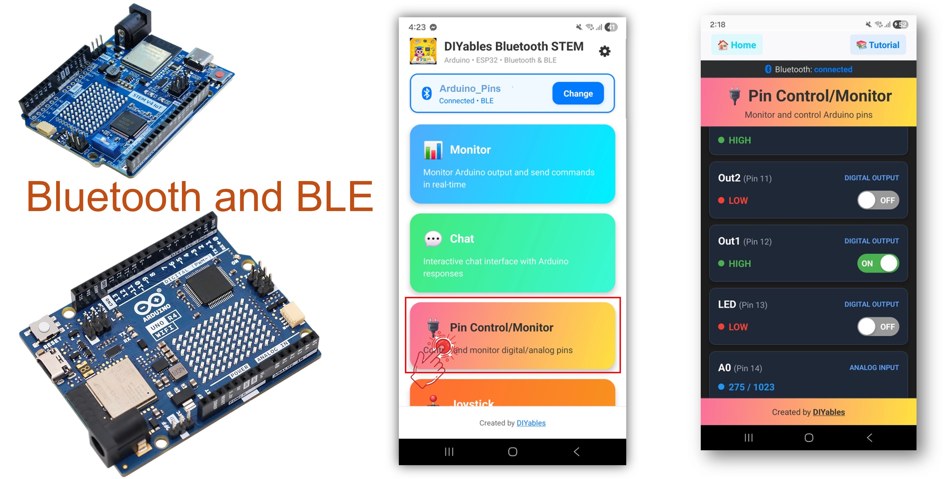
L'exemple Bluetooth Digital Pins offre un contrôle et une surveillance des broches GPIO à distance, accessibles via l'application DIYables Bluetooth STEM. Conçu pour Arduino UNO R4 WiFi utilisant BLE (Bluetooth Low Energy) pour contrôler les broches de sortie et surveiller les broches d'entrée sans fil depuis votre smartphone. Parfait pour le contrôle de relais, la surveillance de boutons, la commutation de LED et toute application nécessitant un accès distant aux broches.
Note : L'Arduino UNO R4 WiFi ne supporte que BLE (Bluetooth Low Energy). Il ne supporte pas le Bluetooth Classic. L'application DIYables Bluetooth supporte à la fois BLE et Bluetooth Classic sur Android, et BLE sur iOS. Puisque cette carte utilise BLE, l'application fonctionne sur Android et iOS.
Fonctionnalités
- Contrôle de Sortie : Définir les broches digitales HIGH/LOW à distance
- Surveillance d'Entrée : Lire les états des broches digitales et analogiques
- Broches Nommées : Assigner des noms conviviaux à chaque broche (ex. "LED", "Relais")
- Mises à jour Temps Réel : Pousser les changements d'état des broches vers l'application
- Jusqu'à 16 Broches : Contrôler plusieurs broches simultanément
- Fonctionne sur Android et iOS : BLE est supporté sur les deux plateformes
- Pas d'Appairage Requis : BLE se connecte automatiquement sans appairage manuel
Matériel Requis
Ou vous pouvez acheter les kits suivants:
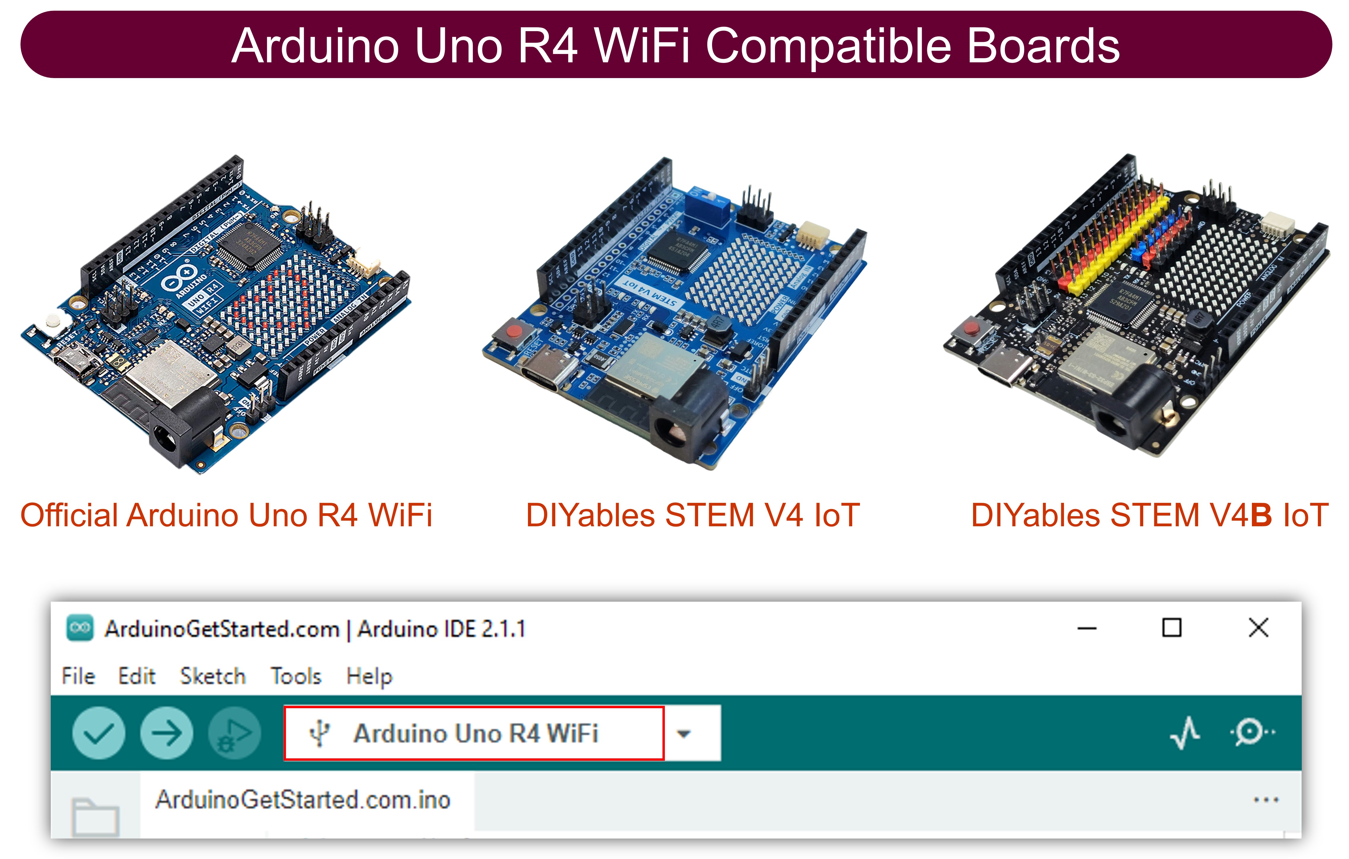
| 1 | × | Kit de Démarrage DIYables STEM V4 IoT (Arduino inclus) | |
| 1 | × | Kit de Capteurs DIYables (18 capteurs/écrans) |
Code Arduino UNO R4 WiFi
Étapes Rapides
Suivez ces instructions étape par étape :
- Si c'est votre première fois avec l'Arduino UNO R4 WiFi, consultez le Arduino UNO R4 - Installation du logiciel..
- Connectez la carte Arduino UNO R4 WiFi à votre ordinateur avec un câble USB.
- Lancez l'IDE Arduino sur votre ordinateur.
- Sélectionnez la carte Arduino UNO R4 WiFi et le port COM approprié.
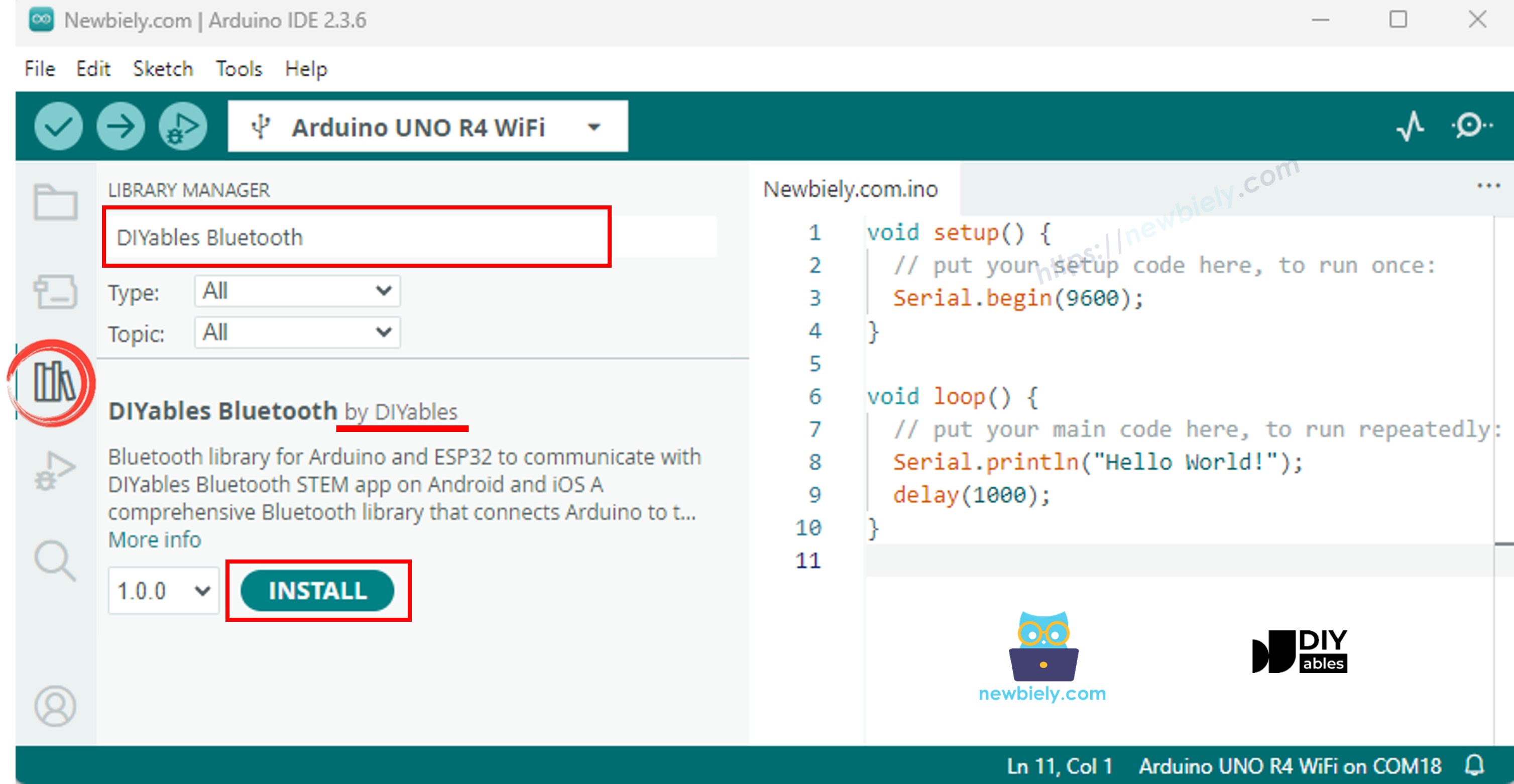
- Naviguez vers l'icône Libraries dans la barre de gauche de l'IDE Arduino.
- Recherchez "DIYables Bluetooth", puis trouvez la bibliothèque DIYables Bluetooth par DIYables
- Cliquez sur le bouton Install pour installer la bibliothèque.
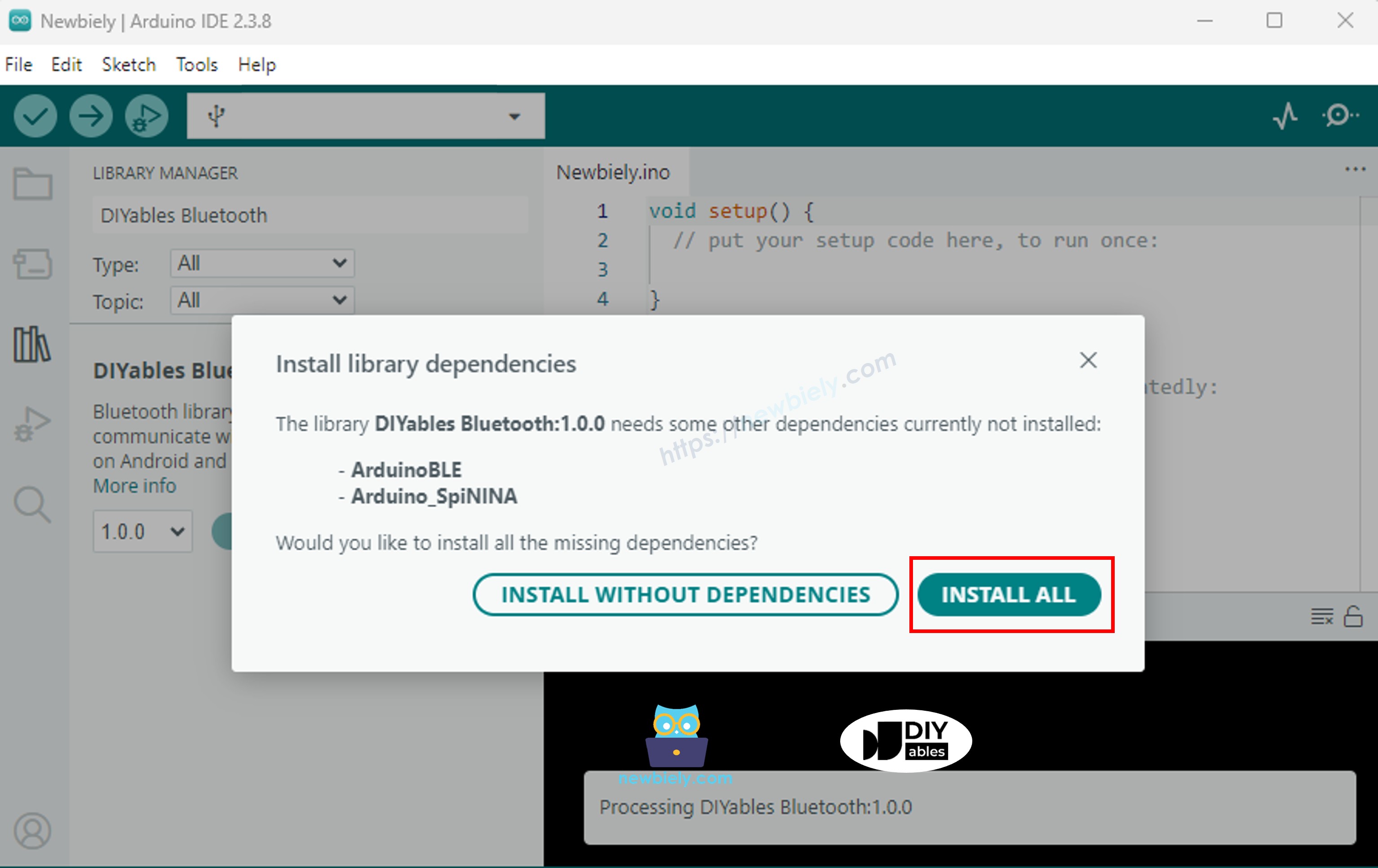
- Il vous sera demandé d'installer d'autres dépendances de bibliothèque
- Cliquez sur le bouton Install All pour installer toutes les dépendances de bibliothèque.
Code BLE
- Dans l'IDE Arduino, allez à File Examples DIYables Bluetooth ArduinoBLE_PinControl exemple, ou copiez le code ci-dessus et collez-le dans l'éditeur de l'IDE Arduino
- Cliquez sur le bouton Upload dans l'IDE Arduino pour téléverser le code vers Arduino UNO R4 WiFi
- Ouvrez le Serial Monitor
- Vérifiez le résultat sur Serial Monitor. Il ressemble à ceci :
Application Mobile
Note : L'application DIYables Bluetooth supporte à la fois BLE et Bluetooth Classic sur Android, et BLE sur iOS. Puisque l'Arduino UNO R4 WiFi utilise BLE, l'application fonctionne sur Android et iOS. Aucun appairage manuel n'est nécessaire pour BLE — il suffit de scanner et se connecter.
- Ouvrez l'application DIYables Bluetooth
- Lors de la première ouverture de l'application, elle demandera des permissions. Veuillez accorder les suivantes :
- Permission Nearby Devices (Android 12+) / permission Bluetooth (iOS) - requise pour scanner et se connecter aux appareils Bluetooth
- Permission Location (Android 11 et antérieur uniquement) - requise par les anciennes versions Android pour scanner les appareils BLE
- Assurez-vous que le Bluetooth est activé sur votre téléphone
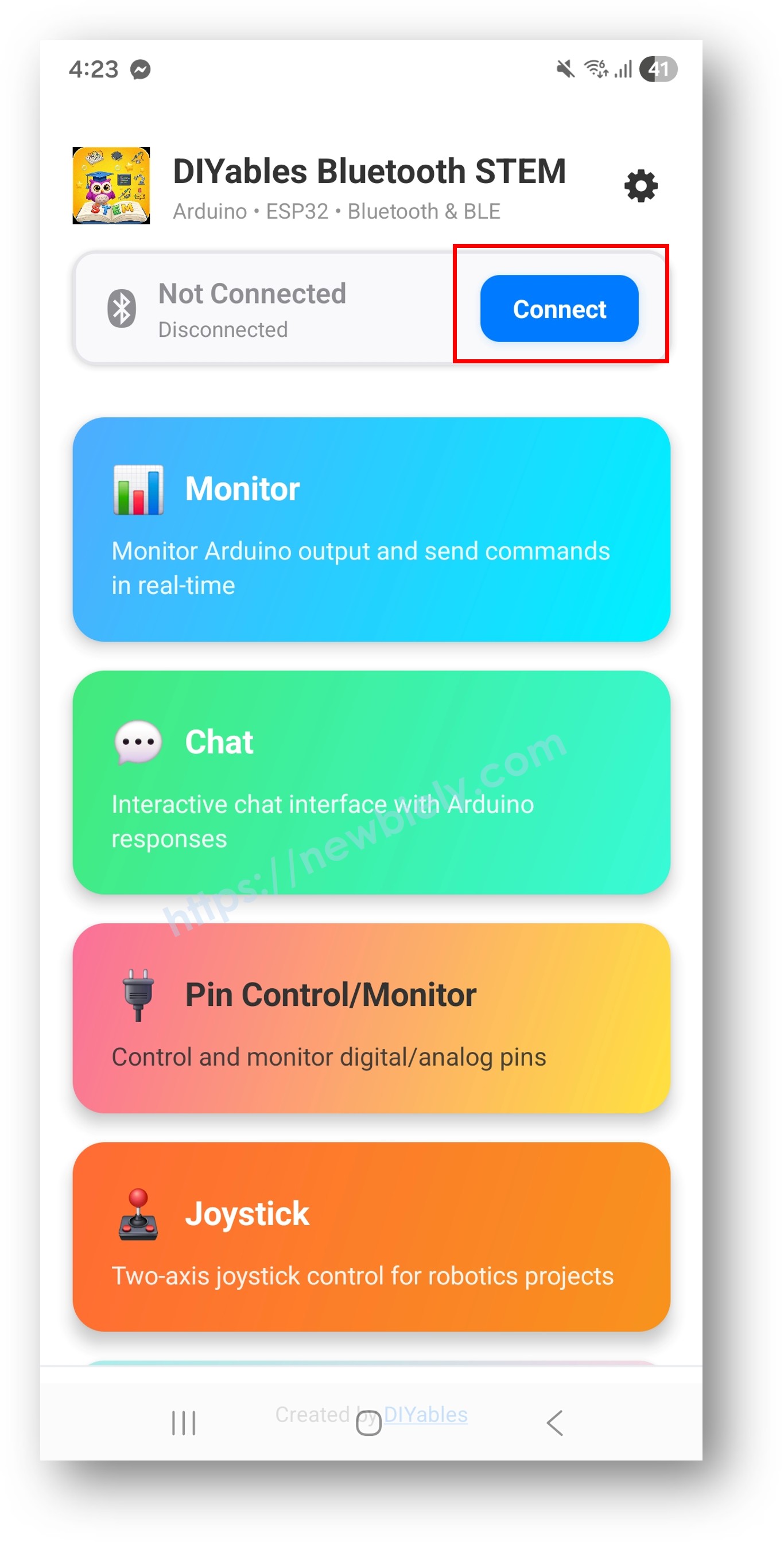
- Sur l'écran d'accueil, appuyez sur le bouton Connect. L'application va scanner les appareils BLE.
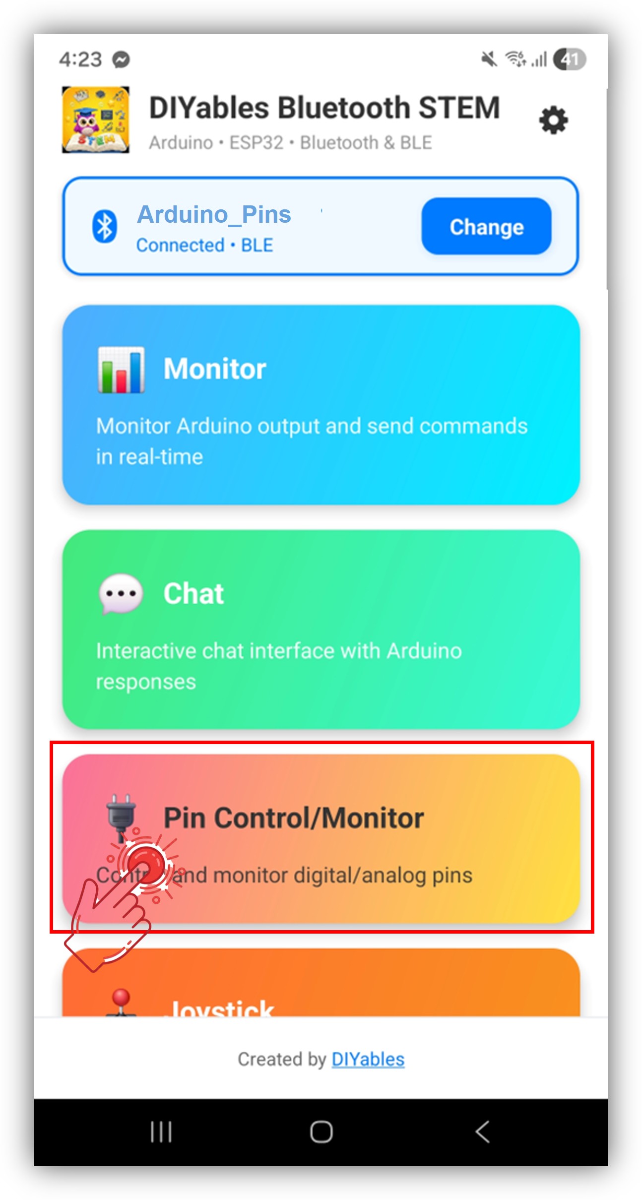
- Trouvez et appuyez sur "Arduino_Pins" dans les résultats de scan pour vous connecter.
- Une fois connecté, l'application revient automatiquement à l'écran d'accueil. Sélectionnez l'application Digital Pins depuis le menu des applications.
Note : Vous pouvez appuyer sur l'icône de paramètres sur l'écran d'accueil pour masquer/afficher les applications sur l'écran d'accueil. Pour plus de détails, consultez le Manuel Utilisateur de l'Application DIYables Bluetooth.
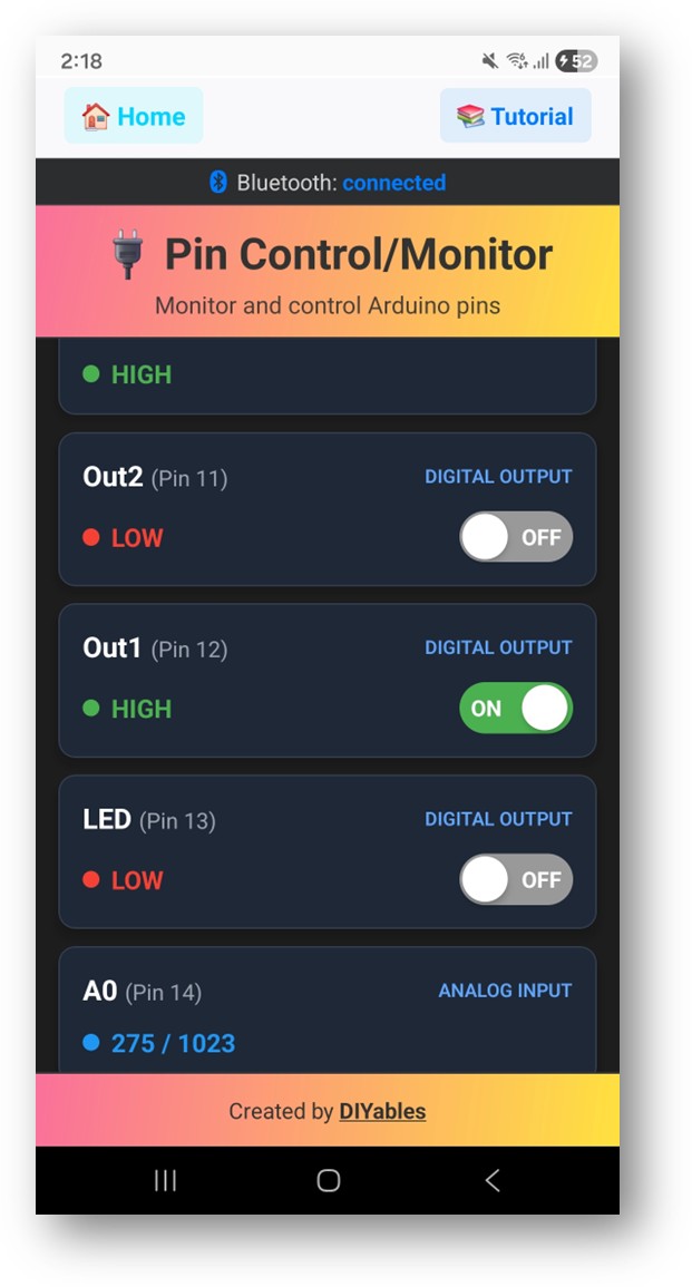
- Vous verrez la liste des broches activées avec leurs noms et états actuels
- Appuyez sur les broches de sortie pour basculer HIGH/LOW, et regardez les valeurs des broches d'entrée se mettre à jour
Maintenant regardez à nouveau le Serial Monitor dans l'IDE Arduino. Vous verrez :
Personnalisation Créative - Adaptez le Code à Votre Projet
Activer les Broches
Gérer l'Écriture/Lecture/Mode des Broches
Pousser les Changements d'État
Exemples de Programmation
Contrôle de Relais avec Surveillance de Bouton
Contrôleur Multi-LED
Dépannage
Problèmes Courants
1. Impossible de trouver l'appareil dans l'application
- Assurez-vous que l'Arduino UNO R4 WiFi est sous tension et que le sketch est téléversé
- Vérifiez que le Bluetooth de votre téléphone est activé
- Sur Android 11 et antérieur, activez aussi les services de localisation
2. Le basculement des broches ne fonctionne pas
- Vérifiez que la broche est activée avec le mode BT_PIN_OUTPUT
- Vérifiez que le callback onPinWrite est configuré
- Vérifiez les connexions de câblage
3. Les broches d'entrée ne se mettent pas à jour
- Assurez-vous que updatePinState() est appelé quand l'état de la broche change
- Vérifiez la fréquence de polling dans la boucle
4. Les valeurs analogiques ne s'affichent pas
- Utilisez analogRead() dans le callback onPinRead pour les broches analogiques
- Les broches analogiques retournent des valeurs 0-1023
5. La connexion se coupe fréquemment
- Rapprochez-vous de l'Arduino (réduire la distance)
- Assurez-vous d'une alimentation USB stable
6. Le téléversement échoue ou la carte n'est pas reconnue
- Installez le dernier package de carte Arduino UNO R4 via Board Manager
- Essayez un câble USB ou port différent
Idées de Projets
- Panneau de contrôle multi-relais
- Moniteur de boutons et interrupteurs
- Contrôleur d'éclairage LED
- Panneau d'interrupteurs domotiques
- Tableau de bord d'entrées capteurs
Étapes Suivantes
Après avoir maîtrisé l'exemple Bluetooth Digital Pins, essayez :
- Bluetooth Slider - Pour le contrôle de valeurs analogiques
- Bluetooth Monitor - Pour les retours de statut textuels
- Bluetooth Table - Pour l'affichage structuré du statut des broches
- Multiples Applications Bluetooth - Combiner le contrôle des broches avec d'autres applications
Support
Pour une aide supplémentaire :
- Consultez la documentation de référence API
- Visitez les tutoriels DIYables
- Forums de la communauté Arduino