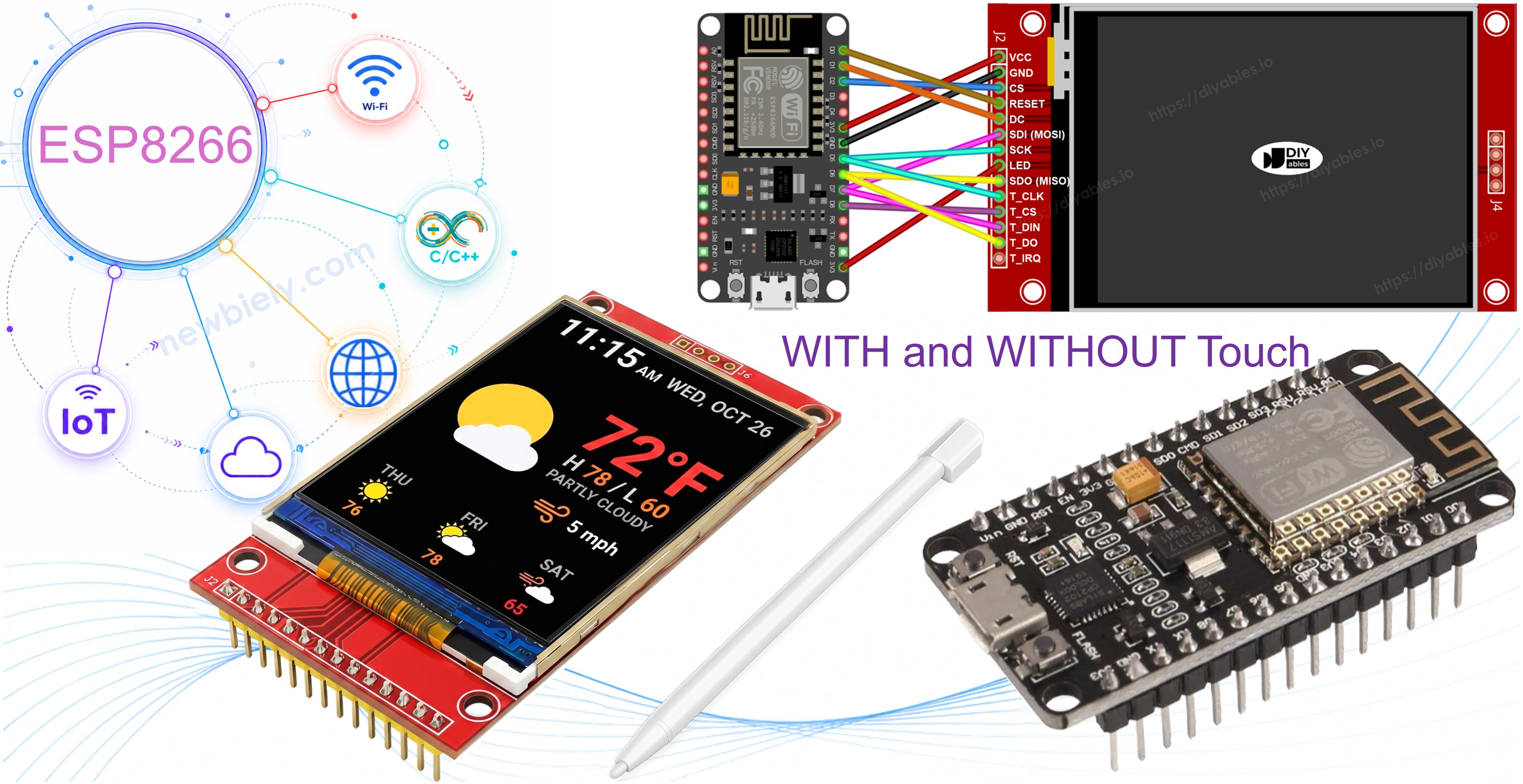
ESP8266 - Écran TFT LCD Tactile SPI ILI9341 ILI9488 ST7789
Voici un guide pratique et sans détour pour connecter un écran TFT SPI à une carte ESP8266 NodeMCU. L'ESP8266 est un microcontrôleur Wi-Fi compact fonctionnant à 80-160 MHz et opérant à 3,3V. Son bus SPI matériel se trouve sur GPIO13 (MOSI), GPIO14 (SCK) et GPIO12 (MISO) — notez que ceux-ci ne sont PAS étiquetés D11/D13/D12 comme les cartes Arduino.
Voici ce que nous allons couvrir :
- Identifier les broches SPI correctes sur l'ESP8266 NodeMCU.
- Câbler en toute sécurité un écran TFT SPI 3,3V.
- Dessiner des formes et des graphiques.
- Afficher du texte et des nombres.
- Dessiner des images bitmap depuis la mémoire programme (PROGMEM).
- Dessiner des images bitmap chargées depuis une carte SD.
- Afficher du texte avec une police externe personnalisée.
- Lire les coordonnées tactiles brutes depuis un contrôleur XPT2046.
- Dessiner sur l'écran par glissement tactile.
- Créer des boutons tactiles interactifs.
- Calibrer l'écran tactile.
- Utiliser un bus SPI secondaire ou personnalisé pour l'afficheur.
Ce tutoriel couvre les écrans TFT LCD SPI tactiles et non tactiles. Il fonctionne avec des panneaux de 1,3, 1,54, 2,2, 2,4, 2,8, 3,2 et 3,5 pouces pilotés par les puces ILI9341, ILI9488 ou ST7789.
Matériel Requis
Ou vous pouvez acheter les kits suivants:
| 1 | × | Kit de Capteurs DIYables (18 capteurs/écrans) |
L'Écran TFT SPI
Les modules TFT SPI utilisent un CI pilote dédié pour recevoir des commandes de dessin et contrôler les pixels LCD via une liaison SPI rapide. Trois pilotes sont pris en charge :
- ILI9341 - couleur RGB565 16 bits, SPI jusqu'à 40 MHz.
- ILI9488 - couleur RGB666 18 bits sur SPI, jusqu'à 24 MHz.
- ST7789 - couleur RGB565 16 bits, SPI jusqu'à 40 MHz.
Recommandation : Si vous n'avez pas encore acheté d'écran, nous recommandons le pilote ST7789. Il est largement disponible, fonctionne à la pleine vitesse SPI de 40 MHz, et constitue le choix le plus simple pour les nouveaux projets.
Les appels de dessin passent par l'API Adafruit GFX : formes, texte, polices et bitmaps sont tous disponibles.
Note : L'ESP8266 fonctionne à 3,3V. Connectez le VCC du TFT à la broche 3,3V. N'appliquez PAS 5V — cela endommagerait la carte.
Avertissement concernant les broches de démarrage : GPIO0, GPIO2 et GPIO15 affectent le mode de démarrage sur l'ESP8266. Évitez de les utiliser pour CS, DC ou RST du TFT afin d'éviter les échecs de téléversement. GPIO4, GPIO5 et GPIO16 sont des choix sûrs.
Brochage
La plupart des écrans TFT LCD SPI ont les broches suivantes :
Broches d'affichage :
| Broche | Fonction |
|---|---|
| VCC | Alimentation |
| GND | Masse |
| CS | Sélection de puce — mis à LOW pour sélectionner l'afficheur sur le bus SPI |
| DC / RS | Sélection Données / Commande — HIGH pour les données pixel, LOW pour les commandes |
| RST | Réinitialisation matérielle — optionnel ; reliez à 3,3V si non utilisé |
| MOSI / SDI / SDA | Données SPI en entrée (MCU → afficheur) |
| SCK / CLK | Horloge SPI |
| MISO / SDO | Données SPI en sortie (afficheur → MCU) — optionnel pour utilisation affichage uniquement |
| LED / BL / BLK | Alimentation rétroéclairage — connecter à 3,3V ou une broche PWM pour le gradateur |
Broches de carte SD (si votre application doit accéder à la carte SD) :
| Broche | Fonction |
|---|---|
| SD_CS / TF_CS | Sélection de puce carte SD |
| MOSI / SDI | MOSI — données du MCU vers la carte SD |
| SCK / CLK | SCK — horloge SPI |
| MISO / SDO | MISO — données de la carte SD vers le MCU |
Pour les écrans TFT prenant en charge le tactile, il y a des broches tactiles supplémentaires :
| Broche | Fonction |
|---|---|
| T_CS | Sélection de puce du contrôleur tactile |
| T_CLK | SCK — horloge SPI |
| T_DIN | MOSI — données du MCU vers le contrôleur tactile |
| T_DO | MISO — données du contrôleur tactile vers le MCU |
| T_IRQ | Interruption tactile — optionnel ; signale quand l'écran est touché |
Note : Certains modules d'affichage non tactiles exposent également les broches T_CS, T_CLK, T_DIN, T_DO et T_IRQ. Celles-ci sont non fonctionnelles sur ces cartes — le CI contrôleur tactile n'est pas implanté. Elles apparaissent car le PCB réutilise la même conception que la version tactile pour réduire les variantes de fabrication.
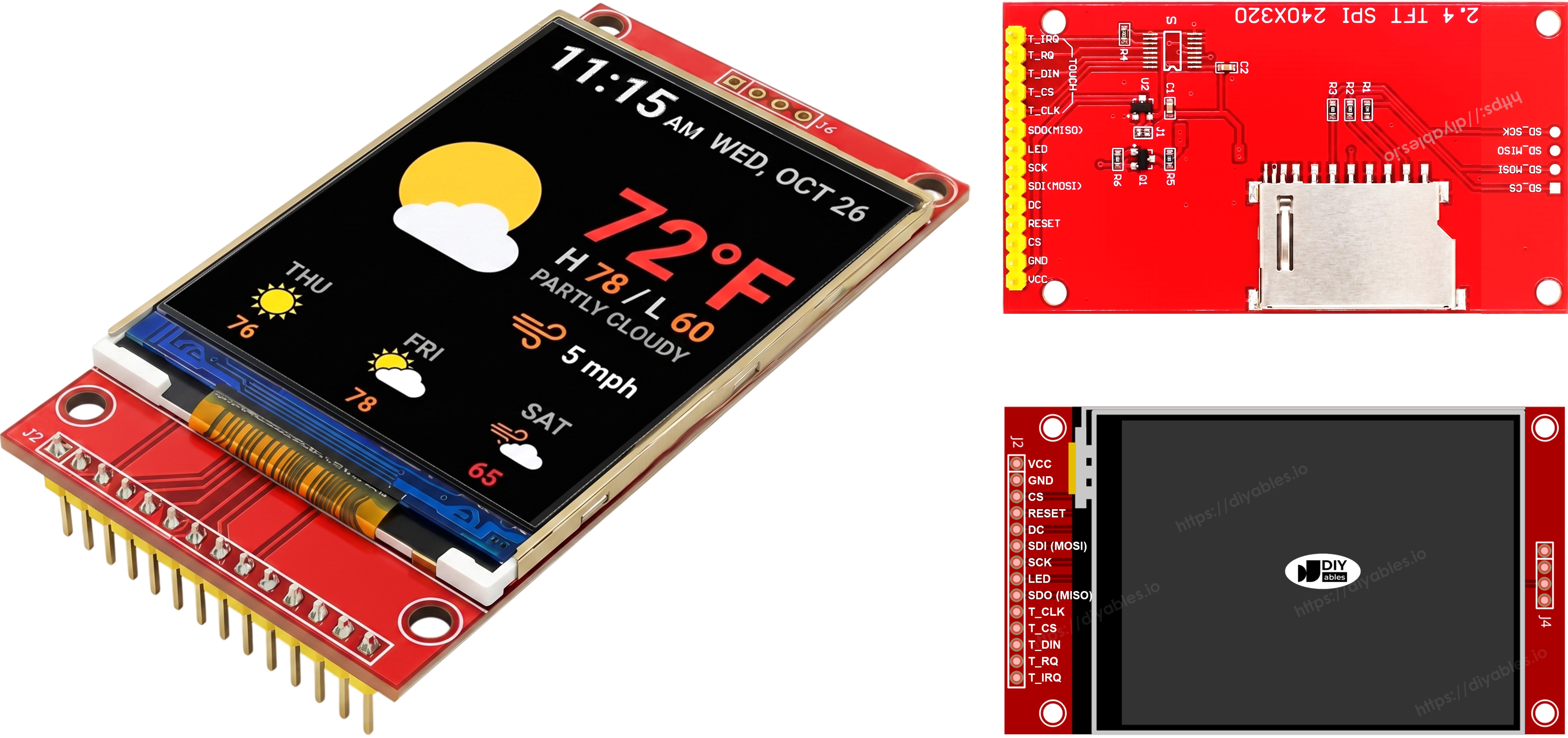
Schéma de Câblage
Sans Tactile
Connectez MOSI à D7 (GPIO13), SCK à D5 (GPIO14), MISO à D6 (GPIO12) sur l'ESP8266 NodeMCU. CS, DC et RST peuvent être n'importe quelle GPIO sûre au démarrage — D2 (GPIO4), D1 (GPIO5), D0 (GPIO16) sont utilisés dans les exemples.
Afficheur :
| Broche TFT | Broche ESP8266 NodeMCU | Numéro GPIO | Description |
|---|---|---|---|
| VCC | 3V3 | - | Alimentation (3,3V uniquement) |
| GND | GND | - | Masse |
| CS | D2 | GPIO4 | Sélection de puce (sûre au démarrage) |
| DC / RS | D1 | GPIO5 | Sélection Données / Commande (sûre au démarrage) |
| RST | D0 | GPIO16 | Réinitialisation (sûre au démarrage, optionnel) |
| MOSI / SDI | D7 | GPIO13 | MOSI SPI matériel |
| SCK | D5 | GPIO14 | Horloge SPI matériel |
| MISO / SDO | D6 | GPIO12 | MISO SPI matériel (optionnel) |
| LED / BL | 3V3 | - | Alimentation rétroéclairage |
Carte SD (si votre application doit accéder à la carte SD) :
| Broche SD | Broche ESP8266 NodeMCU | Numéro GPIO | Description |
|---|---|---|---|
| SD_CS / TF_CS | D8 | GPIO15 | Sélection de puce carte SD (sensible au démarrage — voir note ci-dessous) |
| MOSI / SDI | D7 | GPIO13 | Partagé avec MOSI afficheur (D7/GPIO13) |
| SCK / CLK | D5 | GPIO14 | Partagé avec SCK afficheur (D5/GPIO14) |
| MISO / SDO | D6 | GPIO12 | Partagé avec MISO afficheur (D6/GPIO12) |
⚠ Note broche de démarrage (SD_CS) : GPIO15 (D8) doit être LOW au démarrage. Il est utilisé pour SD_CS dans ces exemples. Les modules SD standard ont une résistance de pull-down qui satisfait automatiquement cette exigence. Si les téléversements cessent de fonctionner après avoir ajouté le module SD, déconnectez le fil SD_CS et réessayez.
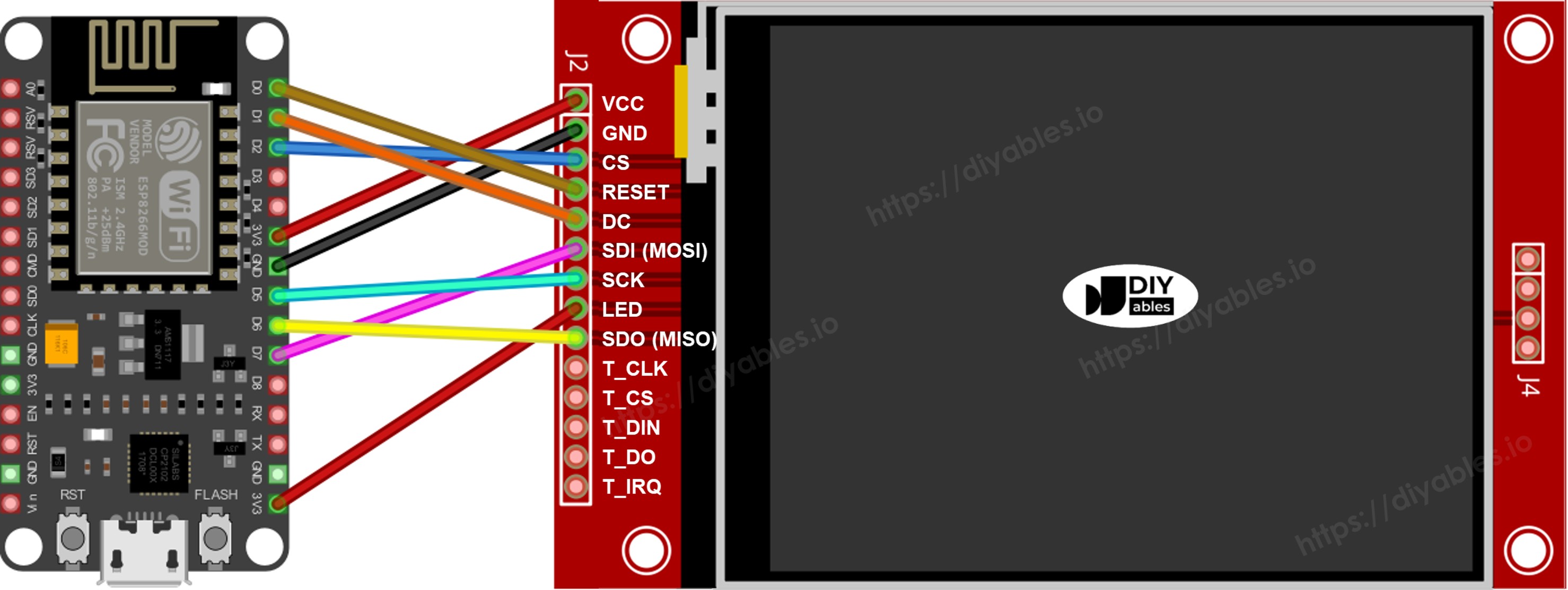
Cette image a été créée avec Fritzing. Cliquez pour agrandir l'image.
Pour plus d'informations, consultez Brochage ESP8266. et Comment alimenter l'ESP8266..
Avec Tactile
Connectez le contrôleur tactile XPT2046 au bus SPI du NodeMCU ESP8266, en partageant D7 (GPIO13), D5 (GPIO14) et D6 (GPIO12) avec l'afficheur.
Afficheur :
| Broche TFT | Broche ESP8266 NodeMCU | Numéro GPIO | Description |
|---|---|---|---|
| VCC | 3V3 | - | Alimentation (3,3V uniquement) |
| GND | GND | - | Masse |
| CS | D2 | GPIO4 | Sélection de puce (sûre au démarrage) |
| DC / RS | D1 | GPIO5 | Sélection Données / Commande (sûre au démarrage) |
| RST | D0 | GPIO16 | Réinitialisation (sûre au démarrage, optionnel) |
| MOSI / SDI | D7 | GPIO13 | MOSI SPI matériel |
| SCK | D5 | GPIO14 | Horloge SPI matériel |
| MISO / SDO | D6 | GPIO12 | MISO SPI matériel (optionnel) |
| LED / BL | 3V3 | - | Alimentation rétroéclairage |
Contrôleur tactile :
| Broche tactile | Broche ESP8266 NodeMCU | Numéro GPIO | Description |
|---|---|---|---|
| T_CS | D3 | GPIO0 | Sélection de puce tactile (sensible au démarrage — voir note ci-dessous) |
| T_IRQ | D4 | GPIO2 | Interruption tactile, optionnel (sensible au démarrage — voir note ci-dessous) |
| T_DIN | D7 | GPIO13 | Partagé avec MOSI afficheur (D7/GPIO13) |
| T_CLK | D5 | GPIO14 | Partagé avec SCK afficheur (D5/GPIO14) |
| T_DO | D6 | GPIO12 | Partagé avec MISO afficheur (D6/GPIO12) |
⚠ Note contrainte broche de démarrage : L'ESP8266 n'a que trois GPIO sûres au démarrage qui ne font pas partie du bus SPI matériel : GPIO4 (D2), GPIO5 (D1) et GPIO16 (D0). Celles-ci sont déjà utilisées par le TFT CS, DC et RST. Chaque broche CS supplémentaire (TOUCH_CS, SD_CS) et le TOUCH_IRQ optionnel doivent donc utiliser une des broches sensibles au démarrage :
- GPIO0 / D3 — doit être HIGH au démarrage. Utilisé pour TOUCH_CS dans ces exemples.
- GPIO2 / D4 — doit être HIGH au démarrage. Utilisé pour TOUCH_IRQ dans ces exemples.
- GPIO15 / D8 — doit être LOW au démarrage. Utilisé pour SD_CS dans ces exemples.
Ces broches sont entièrement utilisables au runtime. Si un module pilote activement l'une de ces broches au mauvais niveau lors de la mise sous tension ou de la réinitialisation, la carte démarrera en mode flash au lieu d'exécuter votre sketch. Si les téléversements cessent de fonctionner après avoir ajouté un module tactile ou SD, déconnectez le fil CS du module et réessayez le téléversement, puis reconnectez.
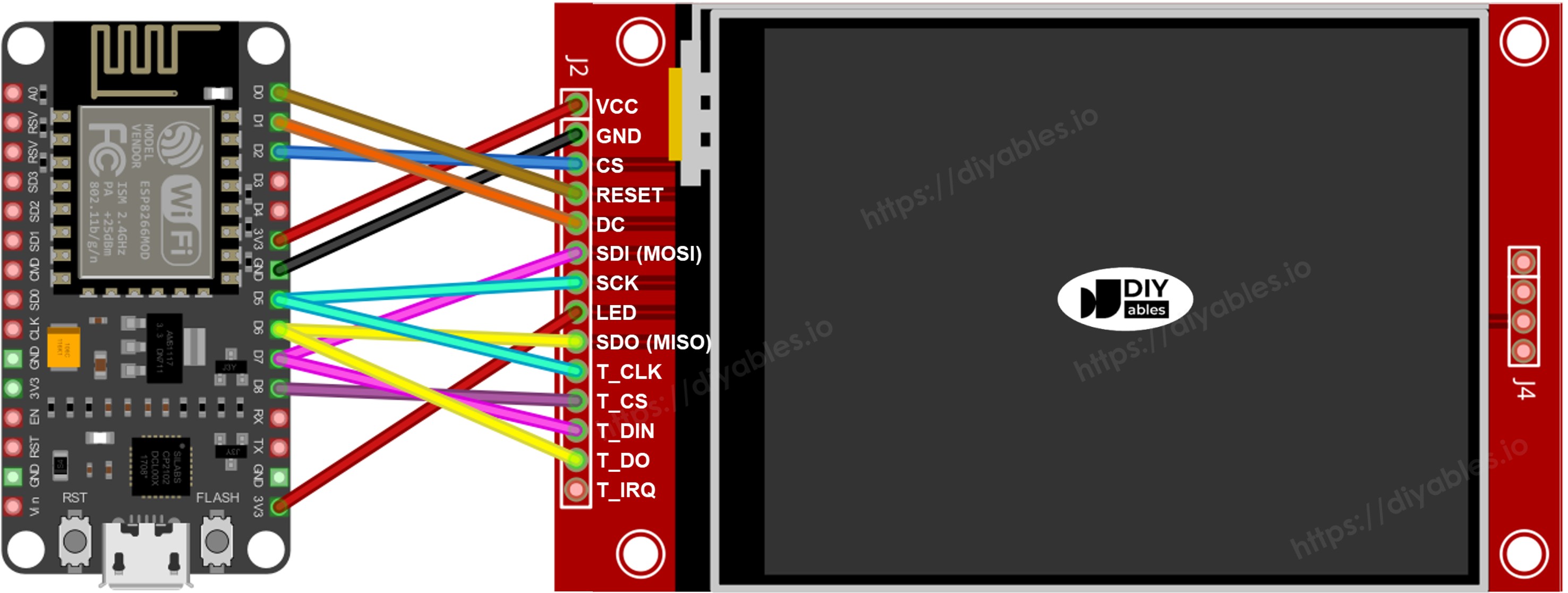
Cette image a été créée avec Fritzing. Cliquez pour agrandir l'image.
Installation de la Bibliothèque
- Connectez le NodeMCU à votre ordinateur avec un câble USB Micro-B.
- Ouvrez l'IDE Arduino. Choisissez NodeMCU 1.0 (ESP-12E Module) dans la liste des cartes et choisissez le bon port.
- Ouvrez le panneau Bibliothèques.
- Tapez "DIYables_TFT_SPI" dans la barre de recherche et trouvez l'entrée DIYables.
- Cliquez sur Installer. Acceptez toutes les installations de dépendances.
- Search for DIYables TFT SPI created by DIYables.io and click the Install button.
Code de Départ
Chaque sketch ESP8266 TFT commence depuis cette base :
Essayez - Dessiner des Formes
L'exemple DrawShapes dessine des cercles, triangles, rectangles, rectangles arrondis et lignes en utilisant l'API de dessin Adafruit GFX.
Exécuter le Code
- Câblez le module TFT au NodeMCU en utilisant le tableau ci-dessus. Alimentation depuis 3,3V uniquement.
- Branchez le câble USB Micro-B.
- Dans l'IDE Arduino, sélectionnez la carte et le port, collez le code et appuyez sur Téléverser.
- L'afficheur montre un motif répétitif de formes colorées.
Fonctions de Dessin
| Méthode | Ce qu'elle dessine | Exemple |
|---|---|---|
| begin() | Initialiser l'afficheur. | TFT_display.begin(); |
| setRotation(r) | Définir l'orientation 0-3. | TFT_display.setRotation(1); |
| fillScreen(color) | Remplir l'écran d'une couleur solide. | TFT_display.fillScreen(BLACK); |
| colorRGB(r,g,b) | Construire une couleur 16 bits depuis R, G, B. | colorRGB(255,200,0) |
| fillCircle(x,y,r,color) | Cercle plein. | TFT_display.fillCircle(80,80,40,RED); |
| fillRect(x,y,w,h,color) | Rectangle plein. | TFT_display.fillRect(10,10,80,50,BLUE); |
| drawFastHLine(x,y,w,color) | Ligne horizontale (rapide). | TFT_display.drawFastHLine(0,120,240,WHITE); |
Essayez - Afficher Texte et Nombre
L'exemple ShowTextAndNumber affiche des chaînes et des valeurs numériques en utilisant le moteur de texte Adafruit GFX.
Exécuter le Code
- Câblez et téléversez comme ci-dessus.
- L'afficheur imprime des lignes de texte dans différentes tailles et couleurs.
Fonctions de Dessin
| Méthode | Ce qu'elle dessine | Exemple |
|---|---|---|
| setTextColor(color) | Définit la couleur du texte en premier plan. | TFT_display.setTextColor(WHITE); |
| setTextSize(size) | Met le texte à l'échelle. Taille 1 = 6×8 px, taille 2 = 12×16 px. | TFT_display.setTextSize(2); |
| setCursor(x, y) | Positionne le curseur de texte au pixel (x, y). | TFT_display.setCursor(10, 20); |
| print(value) | Affiche une chaîne ou un nombre au curseur. | TFT_display.print("NodeMCU!"); |
| println(value) | Affiche et déplace le curseur à la ligne suivante. | TFT_display.println(42); |
Essayez - Afficher une Image
L'exemple DrawImage affiche une image RGB565 couleur stockée dans la flash du programme comme un tableau PROGMEM const uint16_t dans bitmap.h.
Placez bitmap.h dans le même dossier que le sketch avant de compiler.
Exécuter le Code
- Copiez bitmap.h dans le même dossier que le sketch.
- Câblez le module TFT au NodeMCU comme indiqué ci-dessus (GPIO13/14/12 pour SPI, GPIO4/5/16 pour CS/DC/RST). Utilisez 3,3V pour VCC.
- Branchez le câble USB Micro-B.
- Dans l'IDE Arduino, sélectionnez la carte et le port, appuyez sur Téléverser.
- L'afficheur montre l'image bitmap chargée depuis la flash du programme.
Fonctions de Dessin
| Méthode | Ce qu'elle dessine | Exemple |
|---|---|---|
| drawRGBBitmap(x,y,bitmap,w,h) | Affiche un bitmap PROGMEM RGB565 avec son coin supérieur gauche en (x, y). Utilisez le mot-clé PROGMEM sur le tableau. | TFT_display.drawRGBBitmap(0, 0, myImage, 240, 320); |
| fillScreen(color) | Peint tout l'écran d'une couleur solide avant de dessiner. | TFT_display.fillScreen(BLACK); |
Essayez - Afficher une Image depuis la Carte SD
Exécuter le Code
- Câblez le module SD au NodeMCU, partageant GPIO13/14/12 avec l'afficheur. Connectez SD CS à D8 (GPIO15). GPIO15 doit être LOW au démarrage — les modules SD standard satisfont cette exigence avec une résistance de pull-down embarquée.
- Copiez un fichier image binaire RGB565 brut à la racine de la carte SD. Les dimensions doivent correspondre au panneau.
- Branchez le câble USB Micro-B.
- Dans l'IDE Arduino, sélectionnez la carte et le port, appuyez sur Téléverser.
- L'afficheur rend l'image diffusée depuis la carte SD.
Fonctions de Dessin
| Méthode | Ce qu'elle dessine | Exemple |
|---|---|---|
| startWrite() | Ouvre une session d'écriture SPI directe, affirmant le CS de l'afficheur (GPIO4). | TFT_display.startWrite(); |
| setAddrWindow(x0,y0,x1,y1) | Définit la région rectangulaire pour recevoir les données pixel. | TFT_display.setAddrWindow(0, 0, 239, 319); |
| pushColors(buf, len) | Écrit un tampon de valeurs pixel RGB565 sur l'afficheur. Gardez le tampon petit pour rester dans les limites de la mémoire heap. | TFT_display.pushColors(buf, 256); |
| endWrite() | Ferme la session SPI et libère CS. | TFT_display.endWrite(); |
Essayez - Utiliser une Police Externe
Exécuter le Code
- Câblez le module TFT au NodeMCU comme décrit dans la section câblage. Utilisez 3,3V pour VCC.
- Branchez le câble USB Micro-B.
- Dans l'IDE Arduino, sélectionnez la carte et le port, appuyez sur Téléverser.
- L'afficheur rend le texte avec la police personnalisée. La qualité des glyphes est nettement meilleure que la police intégrée.
Fonctions de Dessin
| Méthode | Ce qu'elle dessine | Exemple |
|---|---|---|
| setFont(&FontName) | Bascule vers une police GFX personnalisée. Passer NULL restaure la police intégrée 5×7 pixels. | TFT_display.setFont(&FreeSans12pt7b); |
| setCursor(x, y) | Déplace le curseur de texte à la position pixel donnée. | TFT_display.setCursor(10, 40); |
| setTextColor(color) | Définit la couleur du texte en premier plan. | TFT_display.setTextColor(WHITE); |
| print(text) | Imprime une chaîne au curseur avec la police active. | TFT_display.print("NodeMCU!"); |
Essayez - Obtenir un Point Tactile
Câblage : T_CLK→D5 (GPIO14), T_DIN→D7 (GPIO13), T_DO→D6 (GPIO12). T_CS→D3 (GPIO0), T_IRQ→D4 (GPIO2). Note : GPIO0 et GPIO2 sont des broches de mode de démarrage — elles doivent être HIGH à la mise sous tension. Elles sont sûres à utiliser au runtime. Voir la note contrainte de broche de démarrage dans la section câblage ci-dessus.
Exécuter le Code
- Câblez le XPT2046 au NodeMCU. T_CLK→D5 (GPIO14), T_DIN→D7 (GPIO13), T_DO→D6 (GPIO12), T_CS→D3 (GPIO0), T_IRQ→D4 (GPIO2). GPIO0 et GPIO2 doivent être HIGH à la mise sous tension — voir la note de broche de démarrage dans la section câblage.
- Branchez le câble USB Micro-B.
- Dans l'IDE Arduino, sélectionnez la carte et le port, appuyez sur Téléverser.
- Ouvrez le Moniteur Série à 9600 bauds. Touchez l'afficheur pour voir les valeurs brutes X, Y et pression Z.
Fonctions de Dessin
| Méthode | Ce qu'elle dessine | Exemple |
|---|---|---|
| initTouchSPI(cs, irq) | Initialise le XPT2046 sur le bus SPI partagé. Passez -1 pour irq si la broche d'interruption n'est pas câblée. | TFT_display.initTouchSPI(0, 2); |
| readTouchRaw(x, y, z) | Retourne les valeurs ADC tactiles brutes sans calibration. Retourne true quand l'écran est pressé. | TFT_display.readTouchRaw(x, y, z); |
Essayez - Dessin Tactile
Exécuter le Code
- Câblez le XPT2046 au NodeMCU comme décrit dans la section Obtenir un Point Tactile ci-dessus.
- Branchez le câble USB Micro-B.
- Dans l'IDE Arduino, sélectionnez la carte et le port, appuyez sur Téléverser.
- Faites glisser un doigt sur l'afficheur pour dessiner.
Fonctions de Dessin
| Méthode | Ce qu'elle dessine | Exemple |
|---|---|---|
| initTouchSPI(cs, irq) | Initialise le XPT2046 sur le bus SPI partagé. | TFT_display.initTouchSPI(0, 2); |
| setTouchCalibration(minX,maxX,minY,maxY) | Mappe les valeurs ADC brutes aux coordonnées pixel de l'écran. Obtenez ces nombres depuis l'exemple TouchCalibration. | TFT_display.setTouchCalibration(200, 3800, 300, 3700); |
| setTouchInvertX(invert) / setTouchInvertY(invert) | Inverse l'axe tactile quand X ou Y est en miroir sur votre panneau. Appelez AVANT setTouchCalibration(). | TFT_display.setTouchInvertY(true); |
| getTouch(x, y) | Retourne les coordonnées tactiles calibrées en pixels d'écran. Retourne true pendant que l'écran est pressé. | if (TFT_display.getTouch(x, y)) { ... } |
| fillCircle(x, y, r, color) | Dessine un point à la position tactile pour construire le trait. | TFT_display.fillCircle(x, y, 3, RED); |
Essayez - Bouton Tactile
Exécuter le Code
- Connectez T_CS à D3 (GPIO0). T_IRQ peut rester non connecté (passez -1). GPIO0 doit être HIGH à la mise sous tension — voir la note de broche de démarrage dans la section câblage.
- Branchez le câble USB Micro-B.
- Dans l'IDE Arduino, sélectionnez la carte et le port, appuyez sur Téléverser.
- Appuyez sur les boutons de l'afficheur. Chaque bouton devrait se mettre en surbrillance et déclencher son action.
Fonctions de Dessin
| Méthode | Ce qu'elle dessine | Exemple |
|---|---|---|
| initTouchSPI(cs, irq) | Initialise le XPT2046. Passez -1 pour irq pour utiliser le mode polling. | TFT_display.initTouchSPI(0, -1); |
| setTouchCalibration(minX,maxX,minY,maxY) | Applique la calibration pour que getTouch() retourne des coordonnées en pixels d'écran. | TFT_display.setTouchCalibration(200, 3800, 300, 3700); |
| setTouchInvertX(invert) / setTouchInvertY(invert) | Inverse l'axe tactile quand X ou Y est en miroir sur votre panneau. Appelez AVANT setTouchCalibration(). | TFT_display.setTouchInvertY(true); |
| getTouch(x, y) | Obtient la position tactile calibrée. Retourne true pendant que l'écran est pressé. | if (TFT_display.getTouch(x, y)) { ... } |
| fillRect(x, y, w, h, color) | Dessine un bouton comme un rectangle coloré plein. | TFT_display.fillRect(10, 10, 100, 50, BLUE); |
Essayez - Calibration Tactile
Exécuter le Code
- Câblez le XPT2046 au NodeMCU comme décrit dans la section Obtenir un Point Tactile.
- Branchez le câble USB Micro-B.
- Dans l'IDE Arduino, sélectionnez la carte et le port, appuyez sur Téléverser.
- Ouvrez le Moniteur Série à 9600 bauds. Touchez chaque coin de l'afficheur quand demandé.
- Notez les quatre valeurs imprimées et collez-les dans setTouchCalibration() dans tous les autres sketches tactiles.
Fonctions de Dessin
| Méthode | Ce qu'elle dessine | Exemple |
|---|---|---|
| initTouchSPI(cs, irq) | Initialise le contrôleur XPT2046. | TFT_display.initTouchSPI(0, 2); |
| readTouchRaw(x, y, z) | Lit les valeurs ADC brutes utilisées pour déterminer la plage de calibration. | TFT_display.readTouchRaw(x, y, z); |
| setTouchCalibration(minX,maxX,minY,maxY) | Stocke les valeurs de calibration pour que getTouch() mappe les lectures brutes aux positions pixel correctes. | TFT_display.setTouchCalibration(200, 3800, 300, 3700); |
| setTouchInvertX(invert) / setTouchInvertY(invert) | Inverse l'axe tactile quand X ou Y est en miroir sur votre panneau. Appelez AVANT la calibration. | TFT_display.setTouchInvertY(true); |
Essayez - SPI Personnalisé
Exécuter le Code
- Câblez l'afficheur TFT au NodeMCU comme décrit dans la section câblage. GPIO13/14/12 pour les données, GPIO4/5/16 pour CS/DC/RST.
- Branchez le câble USB Micro-B.
- Dans l'IDE Arduino, sélectionnez la carte et le port, appuyez sur Téléverser.
- L'afficheur démarre sur le bus SPI configuré et montre un motif de test en barres de couleur pour confirmer qu'il fonctionne.
Fonctions de Dessin
| Méthode | Ce qu'elle dessine | Exemple |
|---|---|---|
| DIYables_ILI9341_SPI(w,h,cs,dc,rst,spi) | Constructeur qui accepte un pointeur SPIClass explicite. Omettez le dernier argument pour utiliser &SPI par défaut. | DIYables_ILI9341_SPI tft(240, 320, 4, 5, 16, &SPI); |
| begin() | Initialise l'afficheur sur le bus SPI configuré. | TFT_display.begin(); |
Dépannage
- Écran blanc -- Confirmez que VCC est à 3,3V (pas 5V). Vérifiez MOSI (GPIO13), SCK (GPIO14), CS (GPIO4), DC (GPIO5).
- La carte ne se téléverse plus après avoir ajouté le tactile ou le SD -- GPIO0 (T_CS), GPIO2 (T_IRQ) et GPIO15 (SD_CS) sont des broches de mode de démarrage. Si un module pilote l'une de ces broches au mauvais niveau à la mise sous tension, l'ESP8266 démarre en mode flash au lieu de votre sketch. Déconnectez le fil CS du module, appuyez sur Téléverser, attendez "Connexion en cours...", puis reconnectez.
- La carte ne se téléverse plus (afficheur uniquement) -- TFT CS/DC/RST utilisent des GPIO sûres au démarrage (GPIO4/5/16) et ne devraient pas causer de problèmes de téléversement. Confirmez qu'aucun autre module n'est connecté à GPIO0, GPIO2 ou GPIO15.
- Afficheur déformé -- Un seul constructeur de pilote doit être décommenté. Assurez-vous qu'il correspond à votre panneau.
- Le tactile ne répond pas -- Exécutez d'abord l'exemple TouchCalibration et copiez les valeurs imprimées dans votre sketch.
- Couleurs incorrectes -- Vérifiez que SPI MOSI et SCK ne sont pas inversés.
Support de Plateforme
La bibliothèque utilise uniquement les API Arduino standard et le paramètre architectures=* signifie qu'elle se compile pour l'ESP8266 et toutes les autres plateformes compatibles Arduino.