ESP8266 - Feu de circulation

Ce tutoriel vous explique comment utiliser un ESP8266 pour contrôler un module de feu de circulation. Plus précisément, nous aborderons les aspects suivants :

Préparation du matériel

1×ESP8266 NodeMCU
1×Micro USB Cable
1×Traffic Light Module
1×Jumper Wires
1×(Optional) ESP8266 Screw Terminal Adapter

Or you can buy the following sensor kits:

1×DIYables Sensor Kit (30 sensors/displays)
1×DIYables Sensor Kit (18 sensors/displays)
Divulgation : Certains des liens fournis dans cette section sont des liens affiliés Amazon. Nous pouvons recevoir une commission pour tout achat effectué via ces liens, sans coût supplémentaire pour vous. Nous vous remercions de votre soutien.

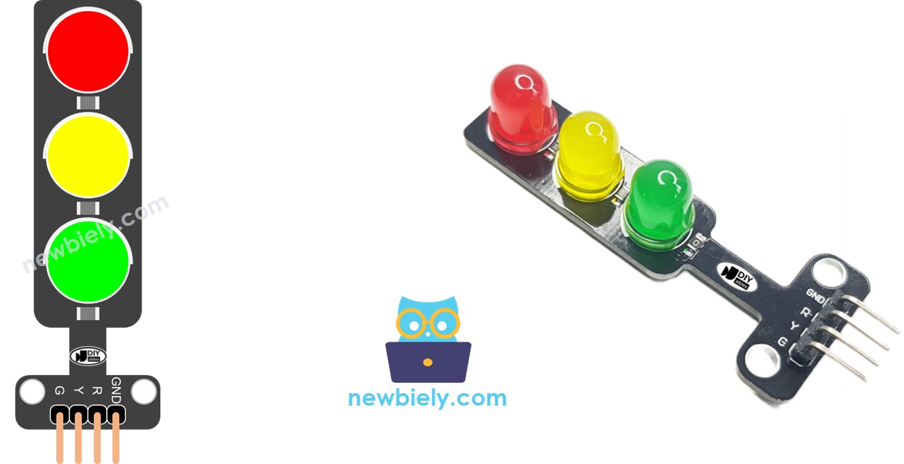
À propos du module de feu de circulation

Brochage

Un module de feu de circulation est équipé de quatre broches :

  • Broche GND : Connectez cette broche à la GND de l'ESP8266.
  • Broche R : Gère la lumière rouge ; connectez cette broche à une sortie numérique de l'ESP8266.
  • Broche Y : Contrôle la lumière jaune ; connectez cette broche à une sortie numérique de l'ESP8266.
  • Broche G : Régule la lumière verte ; connectez cette broche à une sortie numérique de l'ESP8266.
Feu de signalisation Schéma des broches

Comment ça fonctionne

Diagramme de câblage
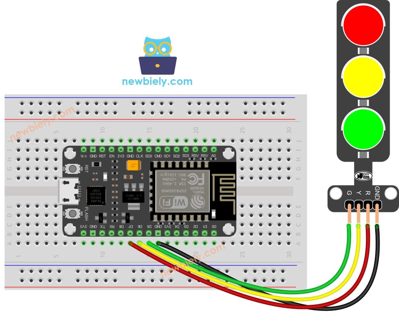
Schéma de câblage des feux de circulation ESP8266 NodeMCU

This image is created using Fritzing. Click to enlarge image

Voir plus dans l'agencement des broches de l'ESP8266 et comment alimenter l'ESP8266 et d'autres composants.

Comment programmer le module de feu de signalisation

  • Configurez les broches d'un ESP8266 en mode sortie numérique en utilisant la fonction pinMode().
pinMode(PIN_RED, OUTPUT); pinMode(PIN_YELLOW, OUTPUT); pinMode(PIN_GREEN, OUTPUT);
  • Programme pour allumer une lumière rouge en utilisant la fonction digitalWrite() :
digitalWrite(PIN_RED, HIGH); // allumer le rouge digitalWrite(PIN_YELLOW, LOW); // digitalWrite(PIN_GREEN, LOW); delay(RED_TIME); // maintenir la LED rouge allumée pendant une période de temps

Code ESP8266

/* * Ce code ESP8266 NodeMCU a été développé par newbiely.fr * Ce code ESP8266 NodeMCU est mis à disposition du public sans aucune restriction. * Pour des instructions complètes et des schémas de câblage, veuillez visiter: * https://newbiely.fr/tutorials/esp8266/esp8266-traffic-light */ #define PIN_RED D7 // The ESP8266 pin connected to R pin of traffic light module #define PIN_YELLOW D6 // The ESP8266 pin connected to Y pin of traffic light module #define PIN_GREEN D5 // The ESP8266 pin connected to G pin of traffic light module #define RED_TIME 4000 // RED time in millisecond #define YELLOW_TIME 4000 // YELLOW time in millisecond #define GREEN_TIME 4000 // GREEN time in millisecond void setup() { pinMode(PIN_RED, OUTPUT); pinMode(PIN_YELLOW, OUTPUT); pinMode(PIN_GREEN, OUTPUT); } // The loop function repeats indefinitely void loop() { // red light on digitalWrite(PIN_RED, HIGH); // turn on digitalWrite(PIN_YELLOW, LOW); // turn off digitalWrite(PIN_GREEN, LOW); // turn off delay(RED_TIME); // keep red light on during a period of time // yellow light on digitalWrite(PIN_RED, LOW); // turn off digitalWrite(PIN_YELLOW, HIGH); // turn on digitalWrite(PIN_GREEN, LOW); // turn off delay(YELLOW_TIME); // keep yellow light on during a period of time // green light on digitalWrite(PIN_RED, LOW); // turn off digitalWrite(PIN_YELLOW, LOW); // turn off digitalWrite(PIN_GREEN, HIGH); // turn on delay(GREEN_TIME); // keep green light on during a period of time }

Étapes rapides

Pour commencer avec l'ESP8266 sur Arduino IDE, suivez ces étapes :

  • Consultez le tutoriel comment configurer l'environnement pour ESP8266 sur Arduino IDE si c'est votre première utilisation de l'ESP8266.
  • Connectez les composants comme indiqué dans le schéma.
  • Branchez la carte ESP8266 à votre ordinateur via un câble USB.
  • Ouvrez Arduino IDE sur votre ordinateur.
  • Sélectionnez la bonne carte ESP8266, comme (par exemple NodeMCU 1.0 (Module ESP-12E)), et son port COM respectif.
  • Copiez le code ci-dessus et ouvrez-le avec Arduino IDE
  • Cliquez sur le bouton Upload sur Arduino IDE pour téléverser le code vers ESP8266
  • Consultez le module de feu de circulation

Il est important de noter que le fonctionnement exact d'un feu de circulation peut varier en fonction du design spécifique et de la technologie utilisée dans différentes régions et intersections. Les principes décrits ci-dessus fournissent une compréhension générale de la manière dont les feux de circulation fonctionnent pour gérer le trafic et améliorer la sécurité sur les routes.

Le code ci-dessus démontre le contrôle individuel des lumières. Maintenant, améliorons le code pour une meilleure optimisation.

Optimisation du code ESP8266

  • Améliorons le code en implémentant une fonction de contrôle de la lumière.
/* * Ce code ESP8266 NodeMCU a été développé par newbiely.fr * Ce code ESP8266 NodeMCU est mis à disposition du public sans aucune restriction. * Pour des instructions complètes et des schémas de câblage, veuillez visiter: * https://newbiely.fr/tutorials/esp8266/esp8266-traffic-light */ #define PIN_RED D7 // The ESP8266 pin connected to R pin of traffic light module #define PIN_YELLOW D6 // The ESP8266 pin connected to Y pin of traffic light module #define PIN_GREEN D5 // The ESP8266 pin connected to G pin of traffic light module #define RED_TIME 2000 // RED time in millisecond #define YELLOW_TIME 1000 // YELLOW time in millisecond #define GREEN_TIME 2000 // GREEN time in millisecond #define RED 0 // Index in array #define YELLOW 1 // Index in array #define GREEN 2 // Index in array const int pins[] = { PIN_RED, PIN_YELLOW, PIN_GREEN }; const int times[] = { RED_TIME, YELLOW_TIME, GREEN_TIME }; void setup() { pinMode(PIN_RED, OUTPUT); pinMode(PIN_YELLOW, OUTPUT); pinMode(PIN_GREEN, OUTPUT); } // The loop function repeats indefinitely void loop() { // red light on trafic_light_on(RED); delay(times[RED]); // keep red light on during a period of time // yellow light on trafic_light_on(YELLOW); delay(times[YELLOW]); // keep yellow light on during a period of time // green light on trafic_light_on(GREEN); delay(times[GREEN]); // keep green light on during a period of time } void trafic_light_on(int light) { for (int i = RED; i <= GREEN; i++) { if (i == light) digitalWrite(pins[i], HIGH); // turn on else digitalWrite(pins[i], LOW); // turn off } }
  • Améliorons le code en utilisant une boucle for.
/* * Ce code ESP8266 NodeMCU a été développé par newbiely.fr * Ce code ESP8266 NodeMCU est mis à disposition du public sans aucune restriction. * Pour des instructions complètes et des schémas de câblage, veuillez visiter: * https://newbiely.fr/tutorials/esp8266/esp8266-traffic-light */ #define PIN_RED D7 // The ESP8266 pin connected to R pin of traffic light module #define PIN_YELLOW D6 // The ESP8266 pin connected to Y pin of traffic light module #define PIN_GREEN D5 // The ESP8266 pin connected to G pin of traffic light module #define RED_TIME 2000 // RED time in millisecond #define YELLOW_TIME 1000 // YELLOW time in millisecond #define GREEN_TIME 2000 // GREEN time in millisecond #define RED 0 // Index in array #define YELLOW 1 // Index in array #define GREEN 2 // Index in array const int pins[] = {PIN_RED, PIN_YELLOW, PIN_GREEN}; const int times[] = {RED_TIME, YELLOW_TIME, GREEN_TIME}; void setup() { pinMode(PIN_RED, OUTPUT); pinMode(PIN_YELLOW, OUTPUT); pinMode(PIN_GREEN, OUTPUT); } // The loop function repeats indefinitely void loop() { for (int light = RED; light <= GREEN; light ++) { trafic_light_on(light); delay(times[light]); // keep light on during a period of time } } void trafic_light_on(int light) { for (int i = RED; i <= GREEN; i ++) { if (i == light) digitalWrite(pins[i], HIGH); // turn on else digitalWrite(pins[i], LOW); // turn off } }
  • Améliorons le code en utilisant la fonction millis() au lieu de delay().
/* * Ce code ESP8266 NodeMCU a été développé par newbiely.fr * Ce code ESP8266 NodeMCU est mis à disposition du public sans aucune restriction. * Pour des instructions complètes et des schémas de câblage, veuillez visiter: * https://newbiely.fr/tutorials/esp8266/esp8266-traffic-light */ #define PIN_RED D7 // The ESP8266 pin connected to R pin of traffic light module #define PIN_YELLOW D6 // The ESP8266 pin connected to Y pin of traffic light module #define PIN_GREEN D5 // The ESP8266 pin connected to G pin of traffic light module #define RED_TIME 2000 // RED time in millisecond #define YELLOW_TIME 1000 // YELLOW time in millisecond #define GREEN_TIME 2000 // GREEN time in millisecond #define RED 0 // Index in array #define YELLOW 1 // Index in array #define GREEN 2 // Index in array const int pins[] = { PIN_RED, PIN_YELLOW, PIN_GREEN }; const int times[] = { RED_TIME, YELLOW_TIME, GREEN_TIME }; unsigned long last_time = 0; int light = RED; // start with RED light void setup() { pinMode(PIN_RED, OUTPUT); pinMode(PIN_YELLOW, OUTPUT); pinMode(PIN_GREEN, OUTPUT); trafic_light_on(light); last_time = millis(); } // The loop function repeats indefinitely void loop() { if ((millis() - last_time) > times[light]) { light++; if (light >= 3) light = RED; // new circle trafic_light_on(light); last_time = millis(); } // TO DO: your other code } void trafic_light_on(int light) { for (int i = RED; i <= GREEN; i++) { if (i == light) digitalWrite(pins[i], HIGH); // turn on else digitalWrite(pins[i], LOW); // turn off } }

Vidéo

Références de fonction

※ OUR MESSAGES

  • Please feel free to share the link of this tutorial. However, Please do not use our content on any other websites. We invested a lot of effort and time to create the content, please respect our work!