ESP8266 - Potentiomètre Buzzer Piézo

Ce tutoriel vous explique comment utiliser l'ESP8266 et un potentiomètre pour contrôler un buzzer piézo. En détail :

Préparation du matériel

1×ESP8266 NodeMCU
1×Micro USB Cable
1×Potentiometer
1×Piezo Buzzer
1×Breadboard
1×Jumper Wires
1×(Optional) 5V Power Adapter for ESP8266
1×(Optional) ESP8266 Screw Terminal Adapter

Or you can buy the following sensor kits:

1×DIYables Sensor Kit (30 sensors/displays)
1×DIYables Sensor Kit (18 sensors/displays)
Divulgation : Certains des liens fournis dans cette section sont des liens affiliés Amazon. Nous pouvons recevoir une commission pour tout achat effectué via ces liens, sans coût supplémentaire pour vous. Nous vous remercions de votre soutien.

À propos du buzzer piézoélectrique et du potentiomètre

Si vous n'êtes pas familier avec le brochage, le fonctionnement et la programmation des buzzers piézoélectriques et des potentiomètres, les tutoriels suivants peuvent vous aider :

Diagramme de câblage
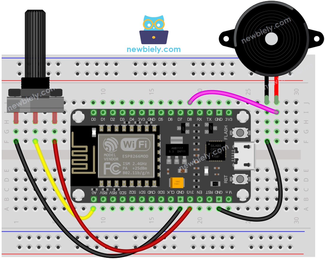
Schéma de câblage du potentiomètre ESP8266 NodeMCU et du buzzer piézo

This image is created using Fritzing. Click to enlarge image

Voir plus dans l'agencement des broches de l'ESP8266 et comment alimenter l'ESP8266 et d'autres composants.

Code ESP8266 - Son Simple - Seuil Analogique

/* * Ce code ESP8266 NodeMCU a été développé par newbiely.fr * Ce code ESP8266 NodeMCU est mis à disposition du public sans aucune restriction. * Pour des instructions complètes et des schémas de câblage, veuillez visiter: * https://newbiely.fr/tutorials/esp8266/esp8266-potentiometer-piezo-buzzer */ #define POTENTIOMETER_PIN A0 // The ESP8266 pin connected to Potentiometer pin #define BUZZER_PIN D8 // The ESP8266 pin connected to Buzzer's pin #define ANALOG_THRESHOLD 1000 void setup() { pinMode(BUZZER_PIN, OUTPUT); // Configure the ESP8266 pin to the output mode } void loop() { int analog_value = analogRead(POTENTIOMETER_PIN); // read the input on analog pin if (analog_value > ANALOG_THRESHOLD) digitalWrite(BUZZER_PIN, HIGH); // turn on Piezo Buzzer else digitalWrite(BUZZER_PIN, LOW); // turn off Piezo Buzzer }

Étapes rapides

Pour commencer avec ESP8266 sur Arduino IDE, suivez ces étapes :

  • Consultez le tutoriel comment configurer l'environnement pour ESP8266 sur Arduino IDE si c'est la première fois que vous utilisez un ESP8266.
  • Câblez les composants comme indiqué dans le schéma.
  • Connectez la carte ESP8266 à votre ordinateur à l'aide d'un câble USB.
  • Ouvrez l'Arduino IDE sur votre ordinateur.
  • Choisissez la bonne carte ESP8266, par exemple (e.g. NodeMCU 1.0 (Module ESP-12E)), et son port COM respectif.
  • Connectez le NodeMCU ESP8266 à l'ordinateur à l'aide d'un câble USB.
  • Ouvrez l'Arduino IDE, sélectionnez la bonne carte et le bon port.
  • Copiez le code et ouvrez-le dans l'Arduino IDE.
  • Cliquez sur le bouton Upload dans l'Arduino IDE pour envoyer le code à l'ESP8266.
  • Tournez le potentiomètre.
  • Écoutez le son émis par le buzzer piézo.

Explication du code

Découvrez l'explication détaillée ligne par ligne contenue dans les commentaires du code source !

Code ESP8266 - Son Simple - Seuil de Tension

La valeur analogique d'un potentiomètre est convertie en une valeur de tension. Ensuite, cette tension est comparée à un seuil de tension, qui activera le buzzer piézoélectrique si le seuil est dépassé.

/* * Ce code ESP8266 NodeMCU a été développé par newbiely.fr * Ce code ESP8266 NodeMCU est mis à disposition du public sans aucune restriction. * Pour des instructions complètes et des schémas de câblage, veuillez visiter: * https://newbiely.fr/tutorials/esp8266/esp8266-potentiometer-piezo-buzzer */ #define POTENTIOMETER_PIN A0 // The ESP8266 pin connected to Potentiometer pin #define BUZZER_PIN D8 // The ESP8266 pin connected to Buzzer's pin #define VOLTAGE_THRESHOLD 2.5 // Voltages void setup() { pinMode(BUZZER_PIN, OUTPUT); // Configure the ESP8266 pin to the output mode } void loop() { int analog_value = analogRead(POTENTIOMETER_PIN); // read the input on analog pin float voltage = floatMap(analog_value, 0, 1023, 0, 5); // Rescale to potentiometer's voltage if (voltage > VOLTAGE_THRESHOLD) digitalWrite(BUZZER_PIN, HIGH); // turn on Piezo Buzzer else digitalWrite(BUZZER_PIN, LOW); // turn off Piezo Buzzer } float floatMap(float x, float in_min, float in_max, float out_min, float out_max) { return (x - in_min) * (out_max - out_min) / (in_max - in_min) + out_min; }

Code ESP8266 - Mélodie - Seuil de Tension

/* * Ce code ESP8266 NodeMCU a été développé par newbiely.fr * Ce code ESP8266 NodeMCU est mis à disposition du public sans aucune restriction. * Pour des instructions complètes et des schémas de câblage, veuillez visiter: * https://newbiely.fr/tutorials/esp8266/esp8266-potentiometer-piezo-buzzer */ #include "pitches.h" #define POTENTIOMETER_PIN A0 // The ESP8266 pin connected to Potentiometer pin #define BUZZER_PIN D8 // The ESP8266 pin connected to Buzzer's pin #define VOLTAGE_THRESHOLD 2.5 // Voltages // notes in the melody: int melody[] = { NOTE_E5, NOTE_E5, NOTE_E5, NOTE_E5, NOTE_E5, NOTE_E5, NOTE_E5, NOTE_G5, NOTE_C5, NOTE_D5, NOTE_E5, NOTE_F5, NOTE_F5, NOTE_F5, NOTE_F5, NOTE_F5, NOTE_E5, NOTE_E5, NOTE_E5, NOTE_E5, NOTE_E5, NOTE_D5, NOTE_D5, NOTE_E5, NOTE_D5, NOTE_G5 }; // note durations: 4 = quarter note, 8 = eighth note, etc, also called tempo: int noteDurations[] = { 8, 8, 4, 8, 8, 4, 8, 8, 8, 8, 2, 8, 8, 8, 8, 8, 8, 8, 16, 16, 8, 8, 8, 8, 4, 4 }; void setup() { } void loop() { int analog_value = analogRead(POTENTIOMETER_PIN); // read the input on analog pin float voltage = floatMap(analog_value, 0, 1023, 0, 5); // Rescale to potentiometer's voltage if (voltage > VOLTAGE_THRESHOLD) playMelody(); // play a song } float floatMap(float x, float in_min, float in_max, float out_min, float out_max) { return (x - in_min) * (out_max - out_min) / (in_max - in_min) + out_min; } void playMelody() { // iterate over the notes of the melody: int size = sizeof(noteDurations) / sizeof(int); for (int thisNote = 0; thisNote < size; thisNote++) { // to calculate the note duration, take one second divided by the note type. //e.g. quarter note = 1000 / 4, eighth note = 1000/8, etc. int noteDuration = 1000 / noteDurations[thisNote]; tone(BUZZER_PIN, melody[thisNote], noteDuration); // to distinguish the notes, set a minimum time between them. // The note's duration + 30% seems to work well: int pauseBetweenNotes = noteDuration * 1.30; delay(pauseBetweenNotes); // stop the tone playing: noTone(BUZZER_PIN); } }

Étapes rapides

  • Câblez les composants comme indiqué dans le schéma.
  • Connectez la carte ESP8266 à votre ordinateur à l'aide d'un câble USB.
  • Ouvrez Arduino IDE sur votre ordinateur.
  • Choisissez la bonne carte ESP8266, comme par exemple le NodeMCU 1.0 (Module ESP-12E), et son port COM respectif.
  • Copiez le code et ouvrez-le avec l'Arduino IDE.
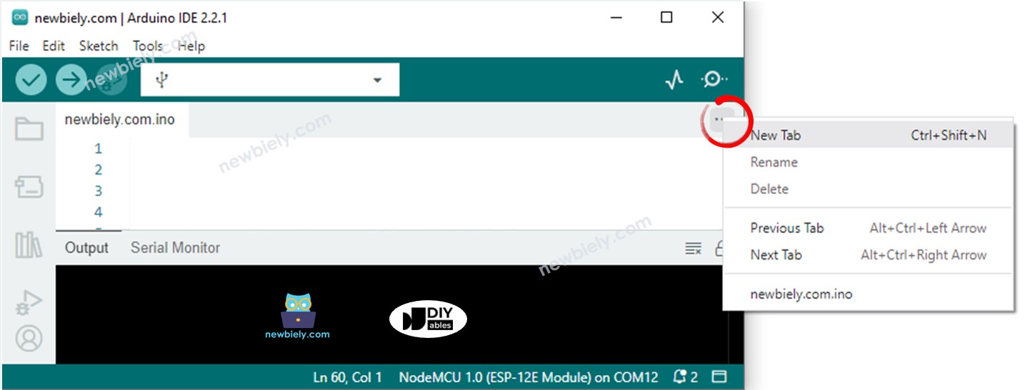
  • Créez le fichier pitches.h sur Arduino IDE en :
    • Cliquant soit sur le bouton juste en dessous de l'icône du moniteur série et choisissez Nouvel Onglet, soit utilisez les touches Ctrl+Shift+N.
    L'IDE Arduino 2 ajoute un fichier.
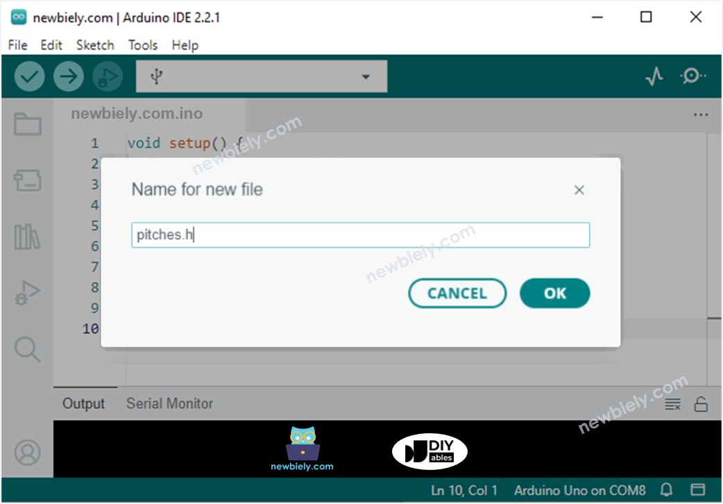
    • Donnez le nom de fichier pitches.h et cliquez sur le bouton OK
    Arduino IDE 2 ajoute le fichier pitches.h
    • Copiez le code ci-dessous et collez-le dans le fichier créé pitches.h.
    /************************************************* * Public Constants *************************************************/ #define NOTE_B0 31 #define NOTE_C1 33 #define NOTE_CS1 35 #define NOTE_D1 37 #define NOTE_DS1 39 #define NOTE_E1 41 #define NOTE_F1 44 #define NOTE_FS1 46 #define NOTE_G1 49 #define NOTE_GS1 52 #define NOTE_A1 55 #define NOTE_AS1 58 #define NOTE_B1 62 #define NOTE_C2 65 #define NOTE_CS2 69 #define NOTE_D2 73 #define NOTE_DS2 78 #define NOTE_E2 82 #define NOTE_F2 87 #define NOTE_FS2 93 #define NOTE_G2 98 #define NOTE_GS2 104 #define NOTE_A2 110 #define NOTE_AS2 117 #define NOTE_B2 123 #define NOTE_C3 131 #define NOTE_CS3 139 #define NOTE_D3 147 #define NOTE_DS3 156 #define NOTE_E3 165 #define NOTE_F3 175 #define NOTE_FS3 185 #define NOTE_G3 196 #define NOTE_GS3 208 #define NOTE_A3 220 #define NOTE_AS3 233 #define NOTE_B3 247 #define NOTE_C4 262 #define NOTE_CS4 277 #define NOTE_D4 294 #define NOTE_DS4 311 #define NOTE_E4 330 #define NOTE_F4 349 #define NOTE_FS4 370 #define NOTE_G4 392 #define NOTE_GS4 415 #define NOTE_A4 440 #define NOTE_AS4 466 #define NOTE_B4 494 #define NOTE_C5 523 #define NOTE_CS5 554 #define NOTE_D5 587 #define NOTE_DS5 622 #define NOTE_E5 659 #define NOTE_F5 698 #define NOTE_FS5 740 #define NOTE_G5 784 #define NOTE_GS5 831 #define NOTE_A5 880 #define NOTE_AS5 932 #define NOTE_B5 988 #define NOTE_C6 1047 #define NOTE_CS6 1109 #define NOTE_D6 1175 #define NOTE_DS6 1245 #define NOTE_E6 1319 #define NOTE_F6 1397 #define NOTE_FS6 1480 #define NOTE_G6 1568 #define NOTE_GS6 1661 #define NOTE_A6 1760 #define NOTE_AS6 1865 #define NOTE_B6 1976 #define NOTE_C7 2093 #define NOTE_CS7 2217 #define NOTE_D7 2349 #define NOTE_DS7 2489 #define NOTE_E7 2637 #define NOTE_F7 2794 #define NOTE_FS7 2960 #define NOTE_G7 3136 #define NOTE_GS7 3322 #define NOTE_A7 3520 #define NOTE_AS7 3729 #define NOTE_B7 3951 #define NOTE_C8 4186 #define NOTE_CS8 4435 #define NOTE_D8 4699 #define NOTE_DS8 4978
    • Cliquez sur le bouton Upload dans l'IDE Arduino pour compiler et téléverser le code vers l'ESP8266.
    • Tournez le potentiomètre.
    • Écoutez la mélodie du buzzer piézo.

    Explication du code

    Découvrez l'explication ligne par ligne contenue dans les commentaires du code source !

    ※ NOTE THAT:

    Le code ci-dessus utilise la fonction delay(). Cela a pour effet de bloquer l'exécution d'autres codes pendant la lecture d'une mélodie. Pour éviter cela, on peut utiliser la bibliothèque ezBuzzer à la place. Cette bibliothèque a été spécifiquement conçue pour permettre à un buzzer de bipper ou de jouer une mélodie sans bloquer les autres codes.

Vidéo

※ OUR MESSAGES

  • Please feel free to share the link of this tutorial. However, Please do not use our content on any other websites. We invested a lot of effort and time to create the content, please respect our work!