ESP8266 - Horloge OLED
Ce tutoriel vous explique comment créer une horloge OLED en utilisant ESP8266, un module RTC et un affichage OLED. Le tutoriel fournit des instructions pour les modules RTC DS3231 et DS1307. En détail :
- ESP8266 obtient l'heure, la minute et la seconde à partir d'un module RTC DS3231 et les affiche sur un OLED.
- ESP8266 obtient l'heure, la minute et la seconde à partir d'un module RTC DS1307 et les affiche sur un OLED.
Vous pouvez choisir entre deux modules RTC : DS3231 et DS1307. Pour plus d'informations, veuillez consulter DS3231 vs DS1307.
Préparation du matériel
Ou vous pouvez acheter les kits suivants:
| 1 | × | Kit de Capteurs DIYables (18 capteurs/écrans) |
Note d'achat: Si vous souhaitez un écran OLED plus grand, utilisez le ESP8266 - Écran OLED SSD1309 128x64 | Tutoriel OLED I2C de 2,42 pouces..
À propos d'OLED, des modules RTC DS3231 et DS1307
Si vous n'êtes pas familier avec les OLED, DS3231 et DS1307 (brochage, fonctionnalités, programmation...), les tutoriels suivants peuvent vous aider :
Installer les bibliothèques OLED et RTC
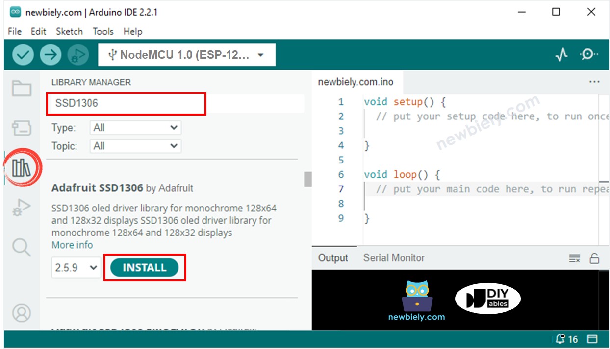
- Cliquez sur l'icône Libraries dans la barre gauche de l'IDE Arduino.
- Recherchez “SSD1306” et trouvez la bibliothèque SSD1306 d'Adafruit.
- Ensuite, appuyez sur le bouton Install pour terminer l'installation.
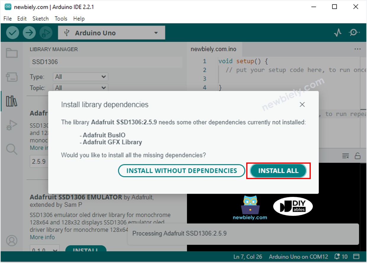
- Vous serez invité à installer des dépendances de bibliothèque supplémentaires.
- Pour les installer toutes en une fois, cliquez sur le bouton Install All.
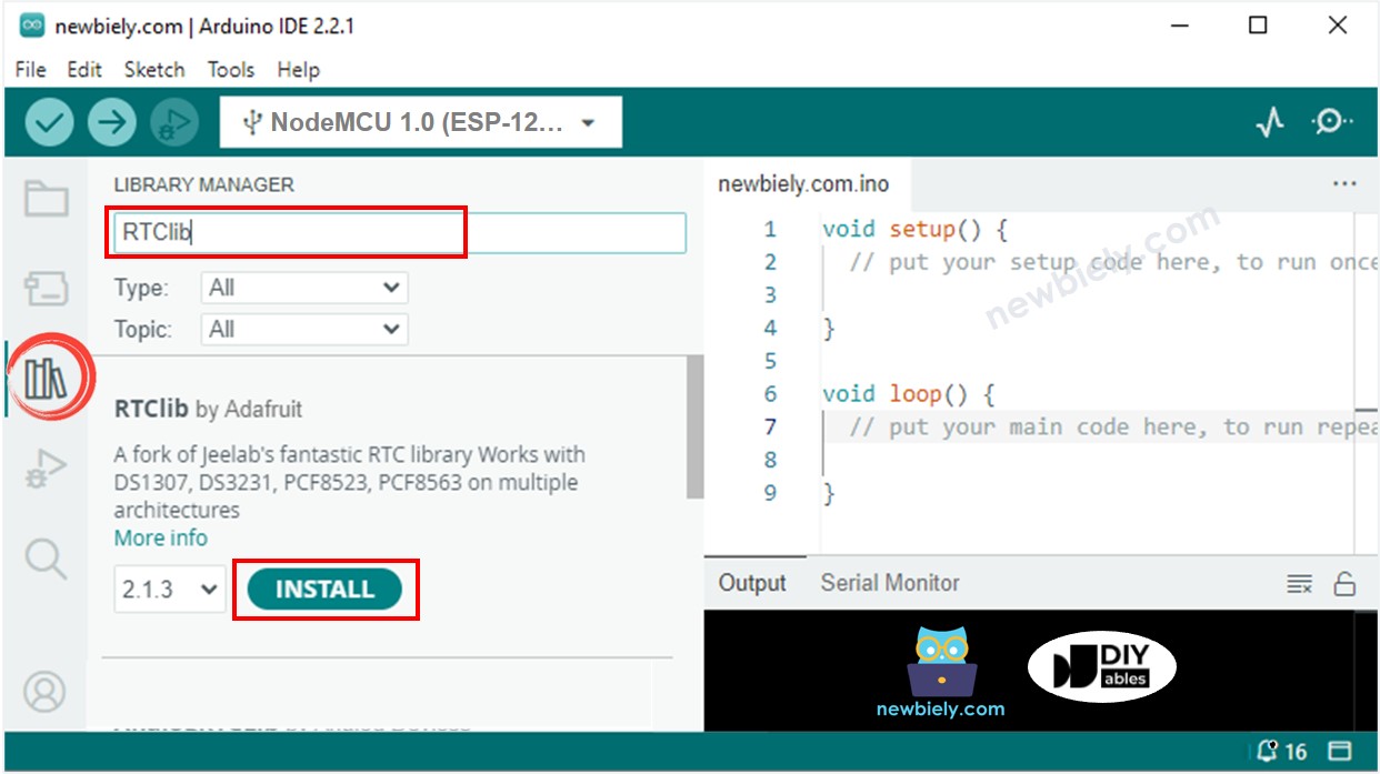
- Recherchez « RTClib » et localisez la bibliothèque RTC d'Adafruit. Cette bibliothèque est compatible avec les DS3231 et DS1307.
- Appuyez sur le bouton Install pour installer la bibliothèque RTC.
Lire l'heure depuis le module RTC DS3231 et l'afficher sur l'OLED
Schéma de câblage
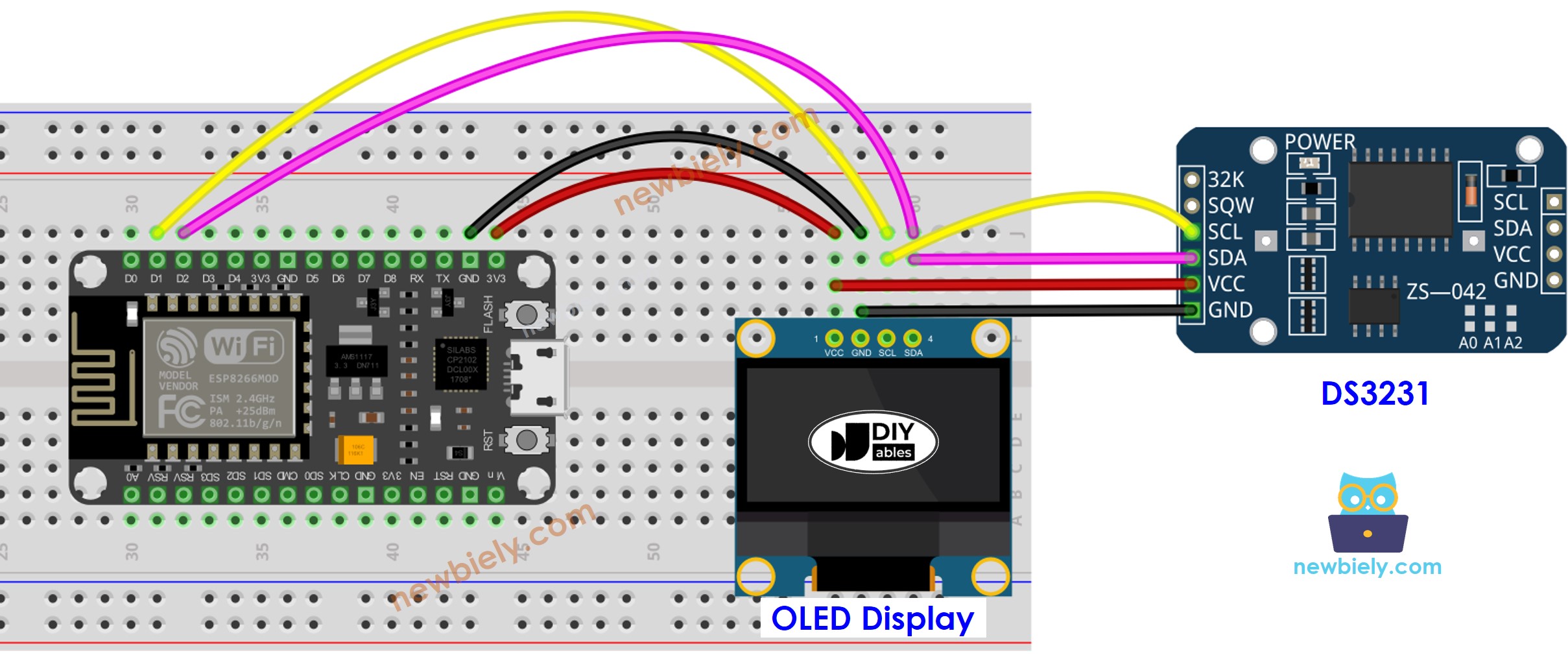
Cette image a été créée avec Fritzing. Cliquez pour agrandir l'image.
Pour plus d'informations, consultez Brochage ESP8266. et Comment alimenter l'ESP8266..
Code ESP8266 - DS3231 et OLED
Étapes rapides
Pour commencer avec ESP8266 sur Arduino IDE, suivez ces étapes :
- Consultez le tutoriel Installation du logiciel ESP8266. si c'est la première fois que vous utilisez ESP8266.
- Câblez les composants comme indiqué dans le schéma.
- Connectez la carte ESP8266 à votre ordinateur à l'aide d'un câble USB.
- Ouvrez Arduino IDE sur votre ordinateur.
- Choisissez la bonne carte ESP8266, comme (par exemple NodeMCU 1.0 (Module ESP-12E)), et son port COM respectif.
- Copiez le code et ouvrez-le avec Arduino IDE.
- Cliquez sur le bouton Upload dans Arduino IDE pour envoyer le code à l'ESP8266.
- Placez le capteur dans de l'eau chaude et froide, ou tenez-le dans votre main.
- Consultez le résultat sur l'OLED.
Lire l'heure depuis le module RTC DS1307 et l'afficher sur l'OLED
Schéma de câblage
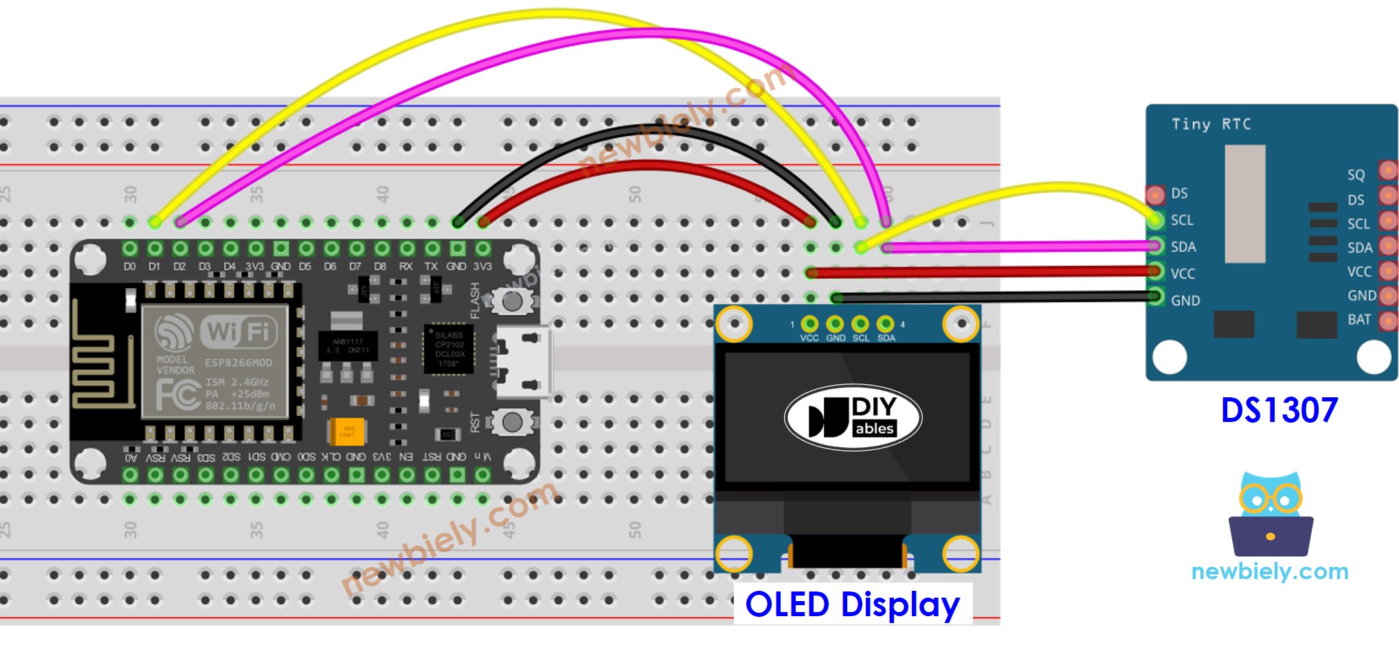
Cette image a été créée avec Fritzing. Cliquez pour agrandir l'image.
Code ESP8266 - DS1307 et OLED
Étapes rapides
- Câblez les composants comme indiqué dans le schéma.
- Connectez la carte ESP8266 à votre ordinateur à l'aide d'un câble USB.
- Ouvrez Arduino IDE sur votre ordinateur.
- Choisissez la bonne carte ESP8266, telle que (par exemple NodeMCU 1.0 (Module ESP-12E)), et son port COM respectif.
- Copiez le code et ouvrez-le dans Arduino IDE.
- Cliquez sur le bouton Upload pour transférer le code vers l'ESP8266.
- Placez le capteur dans de l'eau chaude et froide ou tenez-le dans votre main.
- Consultez le résultat sur l'OLED.