Arduino Mega - Feu de circulation
Dans ce guide, vous apprendrez comment contrôler un module feu de circulation avec un Arduino Mega. Nous couvrirons :
- Comment connecter le module feu de circulation à un Arduino Mega
- Comment programmer un Arduino Mega pour contrôler le feu de circulation
- Comment programmer un Arduino Mega pour contrôler le feu de circulation sans utiliser la fonction delay()
Matériel requis
Ou vous pouvez acheter les kits suivants:
| 1 | × | Kit de Capteurs DIYables (18 capteurs/écrans) |
Divulgation : Certains des liens fournis dans cette section sont des liens affiliés Amazon. Nous pouvons recevoir une commission pour tout achat effectué via ces liens, sans coût supplémentaire pour vous. Nous vous remercions de votre soutien.
À propos du module feu de circulation
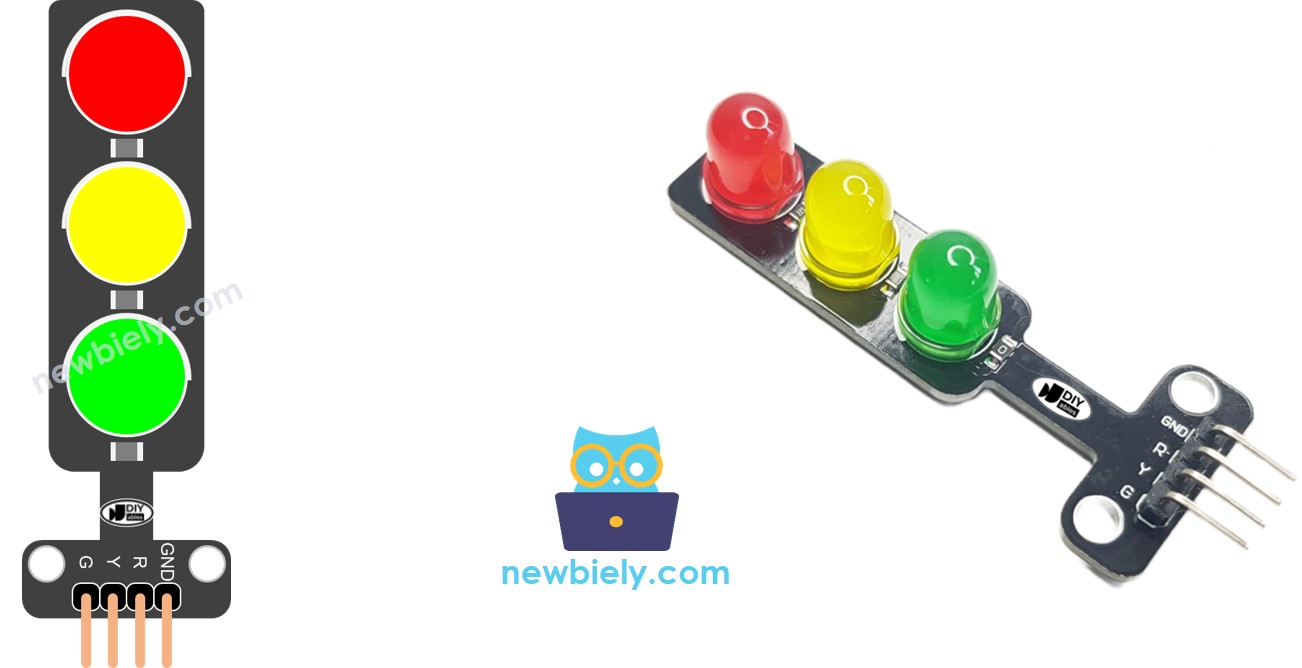
Brochage
Un module feu de circulation possède quatre broches.
- Broche Ground : Il s'agit de la broche de masse. Connectez-la à la masse de l'Arduino Mega.
- Broche Red (R) : Cette broche allume ou éteint le feu rouge. Connectez-la à une sortie numérique de l'Arduino Mega.
- Broche Yellow (Y) : Cette broche allume ou éteint le feu jaune. Connectez-la à une sortie numérique de l'Arduino Mega.
- Broche Green (G) : Cette broche allume ou éteint le feu vert. Connectez-la à une sortie numérique de l'Arduino Mega.
Comment ça fonctionne
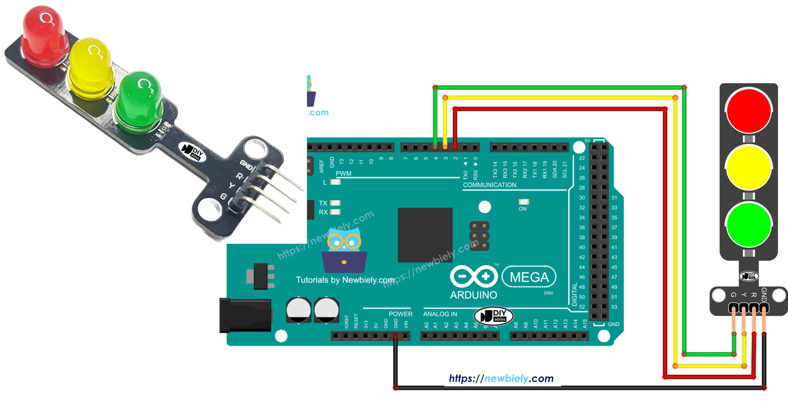
Schéma de câblage
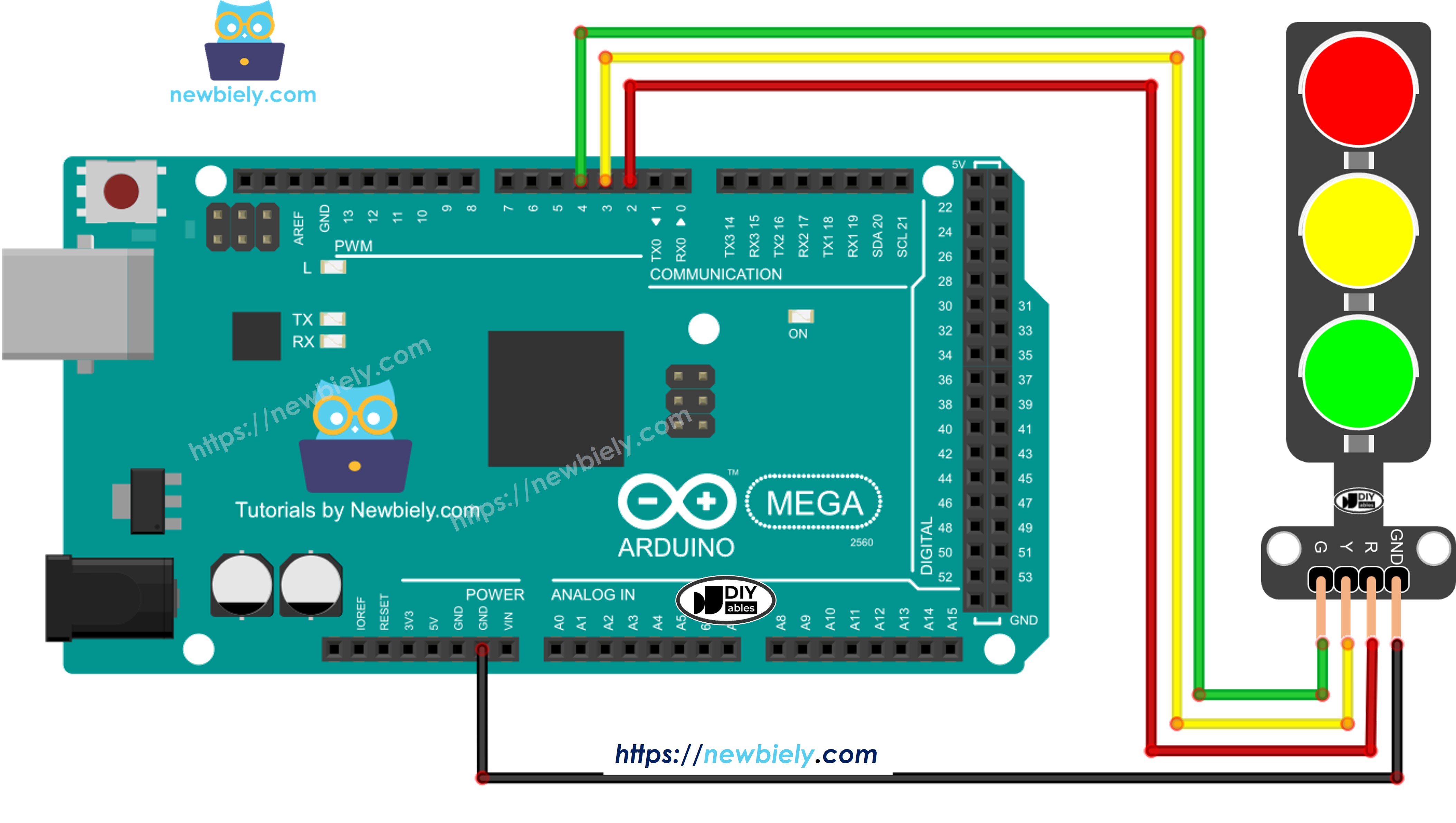
Cette image a été créée avec Fritzing. Cliquez pour agrandir l'image.
Comment programmer pour le module feu de circulation
- Configurez les broches de l'Arduino Mega en sorties numériques en utilisant la fonction pinMode().
pinMode(PIN_RED, OUTPUT);
pinMode(PIN_YELLOW, OUTPUT);
pinMode(PIN_GREEN, OUTPUT);
- Programmez pour allumer le feu rouge en utilisant la fonction digitalWrite().
digital-Write(PIN_RED, HIGH); // Turn the RED LED on
digitalWrite(PIN_YELLOW, LOW); // Turn the YELLOW LED off
digitalWrite(PIN_GREEN, LOW); // Turn the GREEN LED off
delay(RED_TIME); // Keep the RED LED on for RED_TIME milliseconds
Code Arduino Mega
/*
* Ce code Arduino Mega a été développé par newbiely.fr
* Ce code Arduino Mega est mis à disposition du public sans aucune restriction.
* Pour des instructions complètes et des schémas de câblage, veuillez visiter:
* https://newbiely.fr/tutorials/arduino-mega/arduino-mega-traffic-light
*/
#define PIN_RED 2 // The Arduino Mega pin connected to R pin of traffic light module
#define PIN_YELLOW 3 // The Arduino Mega pin connected to Y pin of traffic light module
#define PIN_GREEN 4 // The Arduino Mega pin connected to G pin of traffic light module
#define RED_TIME 4000 // RED time in millisecond
#define YELLOW_TIME 4000 // YELLOW time in millisecond
#define GREEN_TIME 4000 // GREEN time in millisecond
void setup() {
pinMode(PIN_RED, OUTPUT);
pinMode(PIN_YELLOW, OUTPUT);
pinMode(PIN_GREEN, OUTPUT);
}
// the loop function runs over and over again forever
void loop() {
// red light on
digitalWrite(PIN_RED, HIGH); // turn on
digitalWrite(PIN_YELLOW, LOW); // turn off
digitalWrite(PIN_GREEN, LOW); // turn off
delay(RED_TIME); // keep red light on during a period of time
// yellow light on
digitalWrite(PIN_RED, LOW); // turn off
digitalWrite(PIN_YELLOW, HIGH); // turn on
digitalWrite(PIN_GREEN, LOW); // turn off
delay(YELLOW_TIME); // keep yellow light on during a period of time
// green light on
digitalWrite(PIN_RED, LOW); // turn off
digitalWrite(PIN_YELLOW, LOW); // turn off
digitalWrite(PIN_GREEN, HIGH); // turn on
delay(GREEN_TIME); // keep green light on during a period of time
}
Étapes rapides
Suivez ces étapes une par une.
- Connectez le module feu de circulation à l'Arduino Mega en suivant le schéma.
- Connectez la carte Arduino Mega à votre ordinateur avec un câble USB.
- Ouvrez l'IDE Arduino sur votre ordinateur.
- Choisissez la bonne carte (Arduino Mega) et le port correct.
- Copiez le code et ouvrez-le dans l'IDE Arduino.
- Cliquez sur le bouton Téléverser dans l'IDE Arduino pour envoyer le code vers l'Arduino Mega.
- Vérifiez si le module feu de circulation fonctionne.
Les feux de circulation fonctionnent de différentes manières selon leur conception dans chaque endroit. Cette explication simple donne une idée de base de comment les feux de circulation aident à contrôler la circulation.
Le code ci-dessus vous permet de contrôler chaque feu séparément. Maintenant, nous allons améliorer le code pour le rendre plus efficace.
Optimisation du code Arduino Mega
- Améliorons le code en ajoutant une fonction pour allumer et éteindre les feux.
/*
* Ce code Arduino Mega a été développé par newbiely.fr
* Ce code Arduino Mega est mis à disposition du public sans aucune restriction.
* Pour des instructions complètes et des schémas de câblage, veuillez visiter:
* https://newbiely.fr/tutorials/arduino-mega/arduino-mega-traffic-light
*/
#define PIN_RED 2 // The Arduino Mega pin connected to R pin of traffic light module
#define PIN_YELLOW 3 // The Arduino Mega pin connected to Y pin of traffic light module
#define PIN_GREEN 4 // The Arduino Mega pin connected to G pin of traffic light module
#define RED_TIME 2000 // RED time in millisecond
#define YELLOW_TIME 1000 // YELLOW time in millisecond
#define GREEN_TIME 2000 // GREEN time in millisecond
#define RED 0 // Index in array
#define YELLOW 1 // Index in array
#define GREEN 2 // Index in array
const int pins[] = { PIN_RED, PIN_YELLOW, PIN_GREEN };
const int times[] = { RED_TIME, YELLOW_TIME, GREEN_TIME };
void setup() {
pinMode(PIN_RED, OUTPUT);
pinMode(PIN_YELLOW, OUTPUT);
pinMode(PIN_GREEN, OUTPUT);
}
// the loop function runs over and over again forever
void loop() {
// red light on
trafic_light_on(RED);
delay(times[RED]); // keep red light on during a period of time
// yellow light on
trafic_light_on(YELLOW);
delay(times[YELLOW]); // keep yellow light on during a period of time
// green light on
trafic_light_on(GREEN);
delay(times[GREEN]); // keep green light on during a period of time
}
void trafic_light_on(int light) {
for (int i = RED; i <= GREEN; i++) {
if (i == light)
digitalWrite(pins[i], HIGH); // turn on
else
digitalWrite(pins[i], LOW); // turn off
}
}
- Nous pouvons simplifier le code en utilisant une boucle for.
/*
* Ce code Arduino Mega a été développé par newbiely.fr
* Ce code Arduino Mega est mis à disposition du public sans aucune restriction.
* Pour des instructions complètes et des schémas de câblage, veuillez visiter:
* https://newbiely.fr/tutorials/arduino-mega/arduino-mega-traffic-light
*/
#define PIN_RED 2 // The Arduino Mega pin connected to R pin of traffic light module
#define PIN_YELLOW 3 // The Arduino Mega pin connected to Y pin of traffic light module
#define PIN_GREEN 4 // The Arduino Mega pin connected to G pin of traffic light module
#define RED_TIME 2000 // RED time in millisecond
#define YELLOW_TIME 1000 // YELLOW time in millisecond
#define GREEN_TIME 2000 // GREEN time in millisecond
#define RED 0 // Index in array
#define YELLOW 1 // Index in array
#define GREEN 2 // Index in array
const int pins[] = {PIN_RED, PIN_YELLOW, PIN_GREEN};
const int times[] = {RED_TIME, YELLOW_TIME, GREEN_TIME};
void setup() {
pinMode(PIN_RED, OUTPUT);
pinMode(PIN_YELLOW, OUTPUT);
pinMode(PIN_GREEN, OUTPUT);
}
// the loop function runs over and over again forever
void loop() {
for (int light = RED; light <= GREEN; light ++) {
trafic_light_on(light);
delay(times[light]); // keep light on during a period of time
}
}
void trafic_light_on(int light) {
for (int i = RED; i <= GREEN; i ++) {
if (i == light)
digitalWrite(pins[i], HIGH); // turn on
else
digitalWrite(pins[i], LOW); // turn off
}
}
- Améliorons le code en utilisant millis() au lieu de delay().
/*
* Ce code Arduino Mega a été développé par newbiely.fr
* Ce code Arduino Mega est mis à disposition du public sans aucune restriction.
* Pour des instructions complètes et des schémas de câblage, veuillez visiter:
* https://newbiely.fr/tutorials/arduino-mega/arduino-mega-traffic-light
*/
#define PIN_RED 2 // The Arduino Mega pin connected to R pin of traffic light module
#define PIN_YELLOW 3 // The Arduino Mega pin connected to Y pin of traffic light module
#define PIN_GREEN 4 // The Arduino Mega pin connected to G pin of traffic light module
#define RED_TIME 2000 // RED time in millisecond
#define YELLOW_TIME 1000 // YELLOW time in millisecond
#define GREEN_TIME 2000 // GREEN time in millisecond
#define RED 0 // Index in array
#define YELLOW 1 // Index in array
#define GREEN 2 // Index in array
const int pins[] = { PIN_RED, PIN_YELLOW, PIN_GREEN };
const int times[] = { RED_TIME, YELLOW_TIME, GREEN_TIME };
unsigned long last_time = 0;
int light = RED; // start with RED light
void setup() {
pinMode(PIN_RED, OUTPUT);
pinMode(PIN_YELLOW, OUTPUT);
pinMode(PIN_GREEN, OUTPUT);
trafic_light_on(light);
last_time = millis();
}
// the loop function runs over and over again forever
void loop() {
if ((millis() - last_time) > times[light]) {
light++;
if (light >= 3)
light = RED; // new circle
trafic_light_on(light);
last_time = millis();
}
// TO DO: your other code
}
void trafic_light_on(int light) {
for (int i = RED; i <= GREEN; i++) {
if (i == light)
digitalWrite(pins[i], HIGH); // turn on
else
digitalWrite(pins[i], LOW); // turn off
}
}